Bond head for heavy wire bonder

a wire bonding head and heavy wire technology, applied in the direction of soldering apparatus, manufacturing tools, auxillary welding devices, etc., can solve the problems of unstable bond formation, affecting the positioning of wires, and unable to tear large-sized wires, so as to improve the control of wire positioning

Active Publication Date: 2010-07-27
ASM ASSEMBLY AUTOMATION LTD
View PDF31 Cites 10 Cited by
  • Summary
  • Abstract
  • Description
  • Claims
  • Application Information

AI Technical Summary

Benefits of technology

[0008]It is thus an object of the invention to seek to provide a bond head which enhances control of the positioning of wire bonding and wire cutting components of a bond head during wire bonding and wire cutting.

Problems solved by technology

Unlike thin wires, it is not possible to tear a large-sized wire away from the second bond solely by pulling it with a wire clamp after completing wire bonding at the second bond.
The shortcoming of this apparatus is that the flexural disks result in the bonding tool having insufficient rigidity during wire bonding operations, which may lead to unstable bonds being formed.
However, the peak force limit varies with the material selected for providing elasticity.
Therefore, a universal design of the elastic mount for the cutter is not possible for cutting wires of different types and sizes.
If the bond leaves the substrate such that no wire feeding is detected during the pulling test, the bond is defective.
However, detecting wire feeding during such pull test is not reliable as wires may elongate to different extents even for wires of the same material.
This makes the said pull test unreliable as the supposed wire feeding may be due to wire elongation.

Method used


Image

  • Bond head for heavy wire bonder
  • Bond head for heavy wire bonder
  • Bond head for heavy wire bonder

Examples


Embodiment Construction

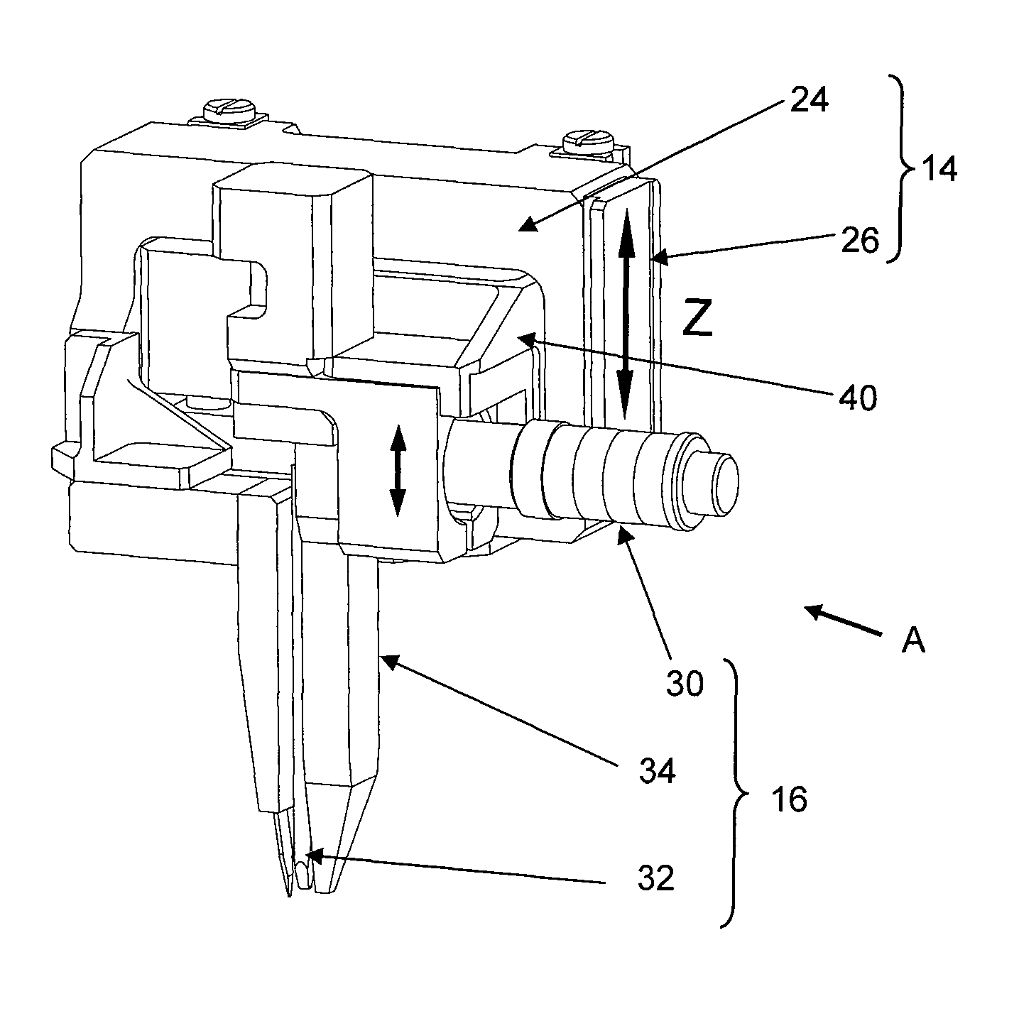
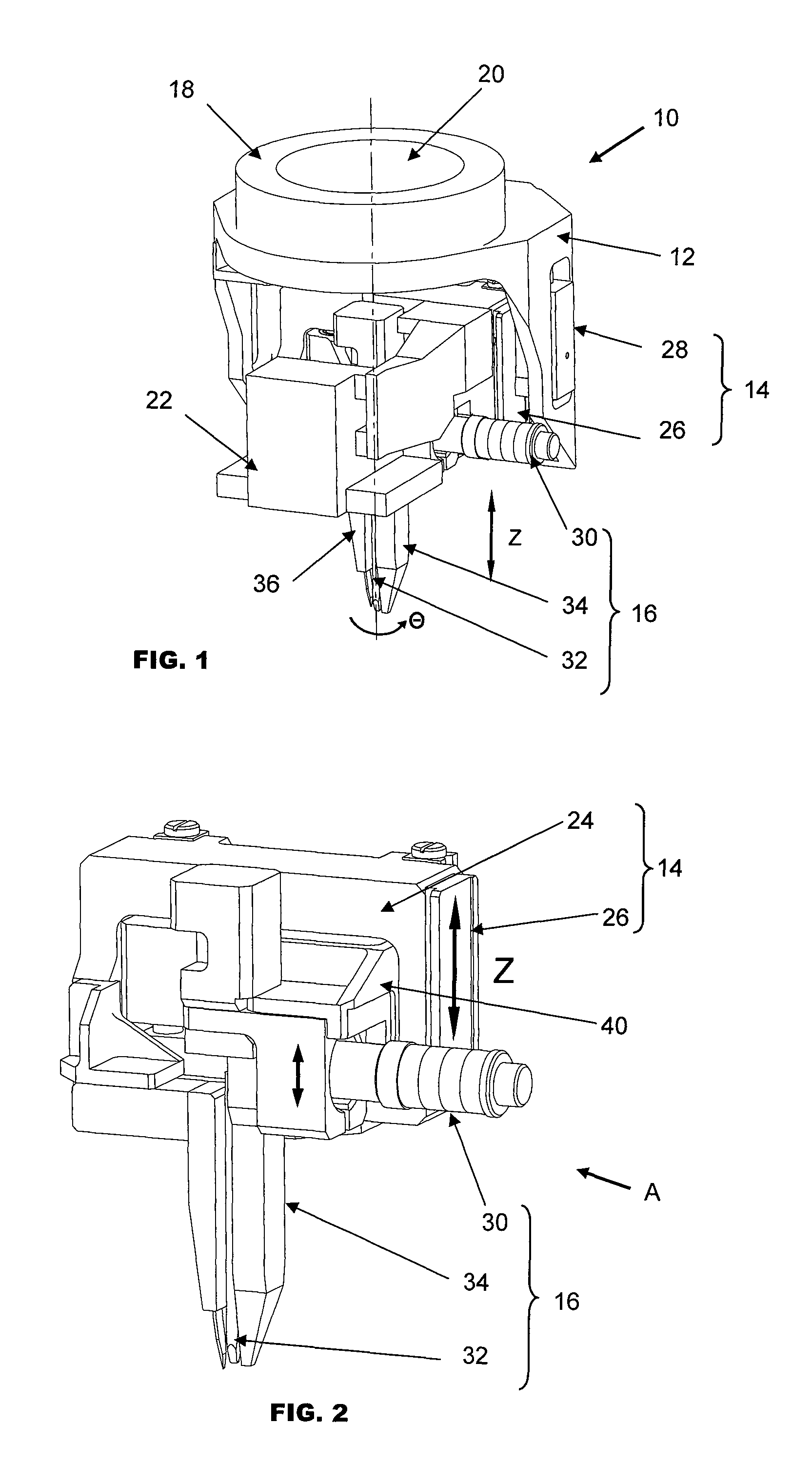
[0027]FIG. 1 is an isometric view of a rotary bond head 10 according to the preferred embodiment of the invention. The bond head 10 comprises three primary modules, namely a bond head mounting bracket 12, a first or main Z module 14 and a second or subsidiary Z module 16. The main Z module 14 and subsidiary Z module 16 are drivable along a linear Z axis towards and away from a bonding point.

[0028]The bond head mounting bracket 12 houses and supports the main Z module 14 of the bond head 10 and is mounted on a rotary motor assembly 18 as well as on an X-Y table (not shown). The rotary motor assembly 18, which may comprise a direct drive motor, is mounted on top of the bond head mounting bracket 12 and drives and rotates a bonding tool in the theta axis about the Z axis to the desired theta orientation before making a first wedge bond. A central opening 20 located in the rotary motor assembly 18 allows a light path parallel to the Z axis to pass from the bonding point through to an op...


PUM

PropertyMeasurementUnit
lengthaaaaaaaaaa
rotationaaaaaaaaaa
reaction forcesaaaaaaaaaa

Abstract

A bonding apparatus for bonding a length of wire comprises a first module which is drivable along a linear axis towards and away from a bonding point and a second module slidably mounted to the first module. A wire cutter is mounted to the first module and a bonding tool is mounted to the second module. A coupling mechanism is operative to lock the second module in fixed relative position to the first module, and to unlock the second module from its fixed relative position to the first module so that the second module is slidable relative to the first module in directions parallel to the linear axis.

Description

FIELD OF THE INVENTION[0001]The invention relates to a bond head for bonding wires to an electronic component with a bonding tool, and in particular to the bonding of wires having relatively large diameters.BACKGROUND AND PRIOR ART[0002]Typically, relatively large and heavy wires such as aluminum wire are used in wedge bonding on high power electronic packages. A bonding machine using wires with such large diameters for bonding generally comprises a bond head that is able to position itself relative to the electronic packages in the X, Y, Z and theta axes for wedge bonding. Having a theta axis is necessary in wedge bonding for aligning the bond orientation with the wire being fed between a first bond and a second bond.[0003]Unlike thin wires, it is not possible to tear a large-sized wire away from the second bond solely by pulling it with a wire clamp after completing wire bonding at the second bond. The wire is usually cut partially by a cutter after the second bond is formed, and ...

Claims


Application Information

Patent Timeline
Patent Type & Authority Patents(United States)
IPC IPC(8): B23K31/02B23K37/00
CPCB23K20/004B23K20/106H01L21/67138H01L24/85H01L24/78B23K2201/42H01L24/45H01L2224/45124H01L2224/48091H01L2224/48472H01L2224/78313H01L2224/78822H01L2224/85H01L2924/01013H01L2924/01033H01L2924/01059H01L2924/01082H01L2924/00014H01L2924/01005H01L2924/00H01L2224/45015H01L2224/85205H01L2224/7855H01L24/48B23K2101/42
Inventor CHENG, CHI WAHMAK, TIM WAI TONYNG, HON KAM BORIS
Owner ASM ASSEMBLY AUTOMATION LTD
Why Eureka
Try Eureka