
Fasteners, railing system and method of assembly

a technology of fasteners and railings, applied in the direction of rod connections, other domestic objects, mechanical devices, etc., can solve the problems of not being suitable for the purposes of an aspect of invention, not having a satisfactory appearance, and inadequate means of affixing pickets to the railings of the fence, etc., to achieve the effect of reducing labor intensity, reducing labor intensity and reducing labor intensity

Inactive Publication Date: 2010-07-27
INTEGRITY COMPOSITES
View PDF37 Cites 28 Cited by
  • Summary
  • Abstract
  • Description
  • Claims
  • Application Information

AI Technical Summary

Benefits of technology

"The invention is about a new type of fastener for assembling picket fences. The fastener has a cylindrical or conical member with screw threads or ridges, and a rectangular or hexagonal member that is connected to it. The fastener can be used to attach pickets to fence rails. The fastener is designed to be hidden from view when assembled, and can be easily installed with minimal tools and effort. The invention also includes a measuring guide for facilitating the spacing of pickets between fence rails. The fastener can be made from a variety of materials, such as plastics, nylon, and metals. Overall, the invention provides a fast and efficient way to assemble picket fences."

Problems solved by technology

However, such method of attachment provides an inadequate means of affixing pickets to fence rails if the fence components are manufactured of certain materials that have limited load-bearing capabilities such as plastic or vinyl.
This method of attachment presents less than a satisfactory appearance as nails and screws may be visible if not properly countersunk and if any brackets are not seated within a depression so that said fasteners and brackets are flush with the surface of the pickets and fence rails.
Even though these designs may be suitable for the specific individual purposes to which they address, they would not be suitable for the purposes of an aspect of the invention.
Additionally, the prior and commercial techniques do not suggest the present inventive combination of component elements arranged and configured as disclosed herein.

Method used


Image

  • Fasteners, railing system and method of assembly
  • Fasteners, railing system and method of assembly
  • Fasteners, railing system and method of assembly

Examples


first embodiment

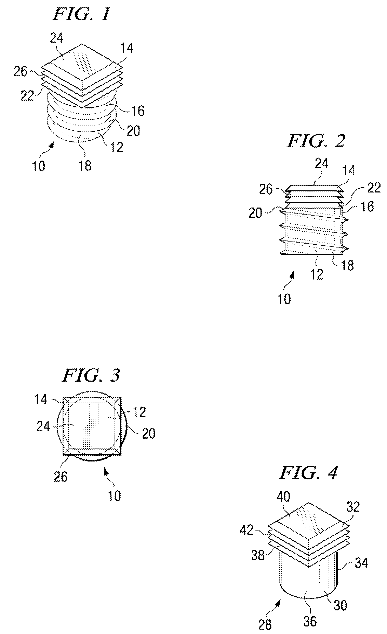
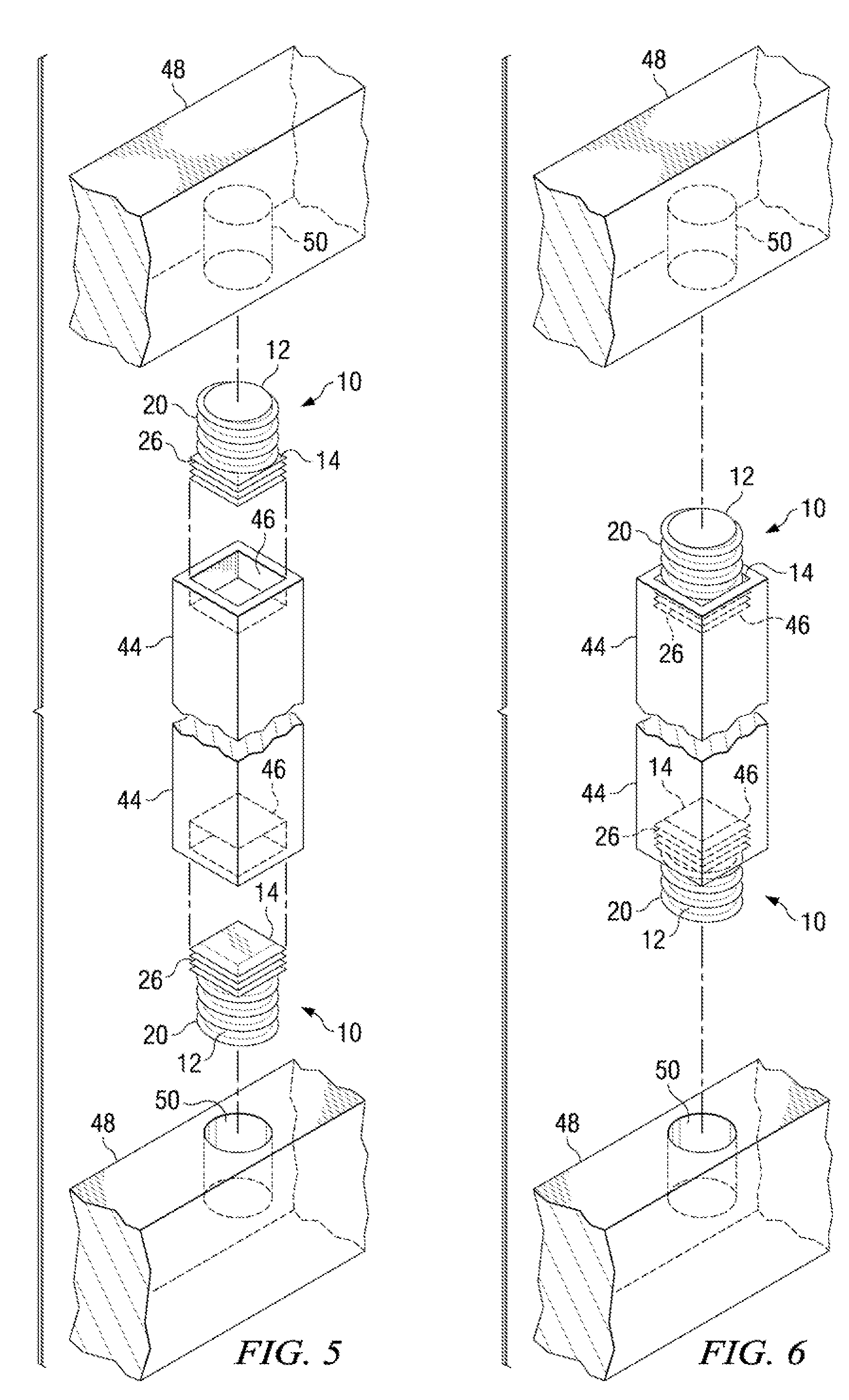
[0034]Referring now to the drawings and, in particular, to FIG. 1 through FIG. 3 wherein there are illustrated a fastener 10 for assembling a picket fence. The fastener 10 is a one-piece, unitary device that is comprised of a cylindrical member 12 and a rectangular member 14. The cylindrical member 12 consists of a first end 16 that is connected to the rectangular member 14 and an opposed second end 18. Screw threads 20 surround the cylindrical member 12. Desirably, fasteners 10 are fabricated of two types: fasteners 10 having screw threads 20 which fasten in a clockwise direction, and fasteners 10 having screw threads 20 which fasten in a counterclockwise direction. The rectangular member is comprised of a first end 22 that is connected to the cylindrical member 12 and a second opposed end 24. A series of parallel ridges 26 is located on the four sidewalls of the rectangular member 14. The rectangular member 14 is desirably sized to fit an opening of a readily available picket 44 (...

second embodiment

[0035]Referring to FIG. 4, therein illustrated is the fastener 28. The fastener 28 is comprised of a cylindrical member 30 and a rectangular member 32, said cylindrical member 30 consisting of a first end 34 connected to the rectangular member 32 and a second opposed end 36. The rectangular member 32 is comprised of a first end 38 that is connected to the cylindrical member 30 and a second opposed end 40. Parallel ridges 42 are located on the four sidewalls of the rectangular member 32.

[0036]The fasteners 10, 28 are comprised of material that is lightweight and durable. Exemplary materials include plastics, nylon, polyvinyl chloride, and other deformable materials including but not limited to synthetic rubber and polyurethane and nondeformable materials such as metals including, but not limited to aluminum, zinc, galvanized steel, carbon steel and stainless steel.

[0037]As displayed in FIG. 5 a picket fence is being assembled with an elongate, rectangular picket 44 having rectangular...

third embodiment

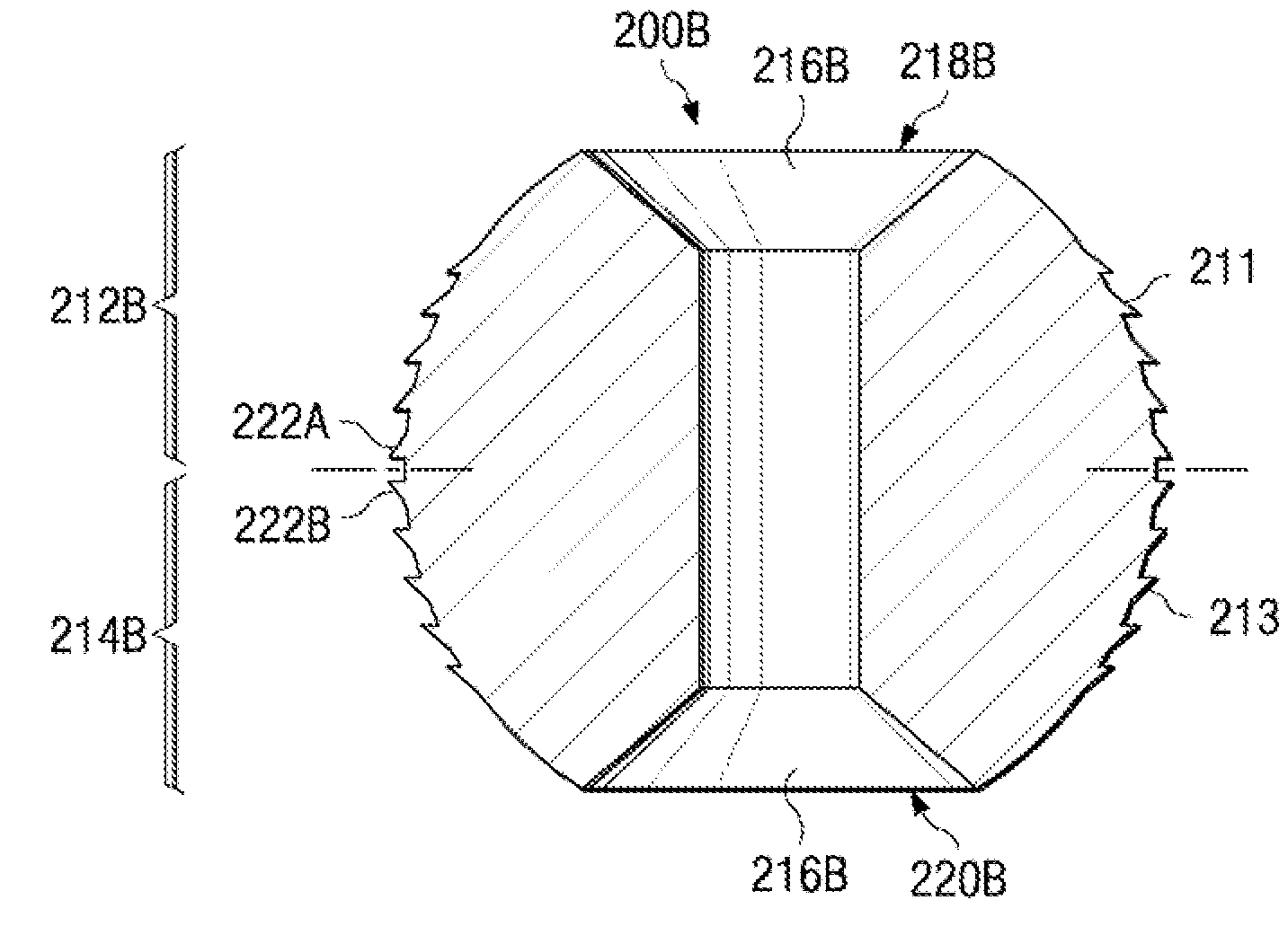
[0040]a fastener 52 is illustrated in FIG. 9 as having a conical member 54 with surrounding screw threads, said conical member 54 tapering from a narrower end to a wider end with said wider end connected to a rectangular member 56. The fastener 52 is aligned between an end of a picket 44 with cooperating bore 46 and a communicating side of a fence rail 58. Two types of fasteners 52 are desirably provided, a first in which the conical member 54 has clockwise-fastening threads, and a second in which the conical member 54 has counterclockwise-fastening threads.

[0041]The picket 44 is attached to upper and lower rails 58 by first inserting the rectangular member 56 of the fastener 52 into the bore 46 at opposed ends of the picket 44 so that the rectangular member 56 frictionally engages the surrounding sidewalls of the bore 46 and anchors the fastener 52 to the picket 44. The picket 44 with the fastener 52 disposed therein is placed adjacent to the rails 58 in perpendicular relation and ...


PUM


Abstract

A fastener is configured to affix a first article such as a picket to a second article such as a rail to form a railing or balustrade. The fastener includes a first engaging surface having a maximum diameter configured to engage an interior surface of an opening in the first article and a mating surface configured to mate with the second article. The first engaging surface can have shape selected from cylindrical, ellipsoidal, conical, elliptic conical frustum, pyramidal frustum, and ball and other shapes having cross-sections of rectangular, pentagonal, hexagonal, octagonal and other regular polygons having at least four sides such that good engagement is obtained and the fastener is hidden from view in the assembled railing.

Description

CROSS-REFERENCE TO RELATED APPLICATIONS[0001]This application is a Continuation Application of U.S. patent application Ser. No. 10 / 613,605, filed Jul. 3, 2003, which claims priority to U.S. Provisional Application Ser. No. 60 / 393,125, filed on Jul. 3, 2002, both of which are commonly assigned with the present application and incorporated herein by reference in their entirety for all purposes.TECHNICAL FIELD[0002]The invention is related to fasteners and methods used to assemble a railing, balustrade or fence. More specifically, the invention is concerned with a fastener that can be affixed to opposing ends of a picket or baluster in order to attach the picket to a pair of rails for assembly of a picket fence or balustrade.BACKGROUND[0003]Picket fences are in widespread use to demarcate property lines and to enclose specific spaces within a property such as a patio, backyard deck, pool, and the like. Such fences incorporate a variety of designs but generally consist of a sequence of ...

Claims


Application Information

Patent Timeline
Patent Type & Authority Patents(United States)
IPC IPC(8): E04H17/14E04F11/18F16B7/18
CPCE04F11/181E04H17/1439F16B7/18E04F2011/1823E04F2011/1827E04F11/1853E04F11/1817E04F2011/1821
Inventor DEROGATIS, DAVIDCONNOR, KEVIN
Owner INTEGRITY COMPOSITES
Learn More