Device and method for calibrating an element and device and system for positioning an element

a technology of element and device, applied in the field of devices and methods for calibrating elements and devices and systems for positioning elements, can solve problems such as scars, increased risk of infection or complications,

Inactive Publication Date: 2010-07-27
BRAINLAB
View PDF9 Cites 22 Cited by
  • Summary
  • Abstract
  • Description
  • Claims
  • Application Information

AI Technical Summary

Benefits of technology

[0011]In one embodiment, the tip of an instrument or element to be calibrated can be calibrated in a known way before the calibrating method is performed, i.e., in addition to the point of the instrument or element to be calibrated, which is connected to the navigation element, the spatial position of another point of the instrument or element to be calibrated is known, thus simplifying the calibrating method. The tip can be calibrated, for example, by moving the tip to a spatial position, which is known.
[0014]The device can, for example, include a plane surface, which the instrument or element to be calibrated can contact. Alternatively, the device can include two or more adjacent planes forming, for example, an edge or a V-shape. The element or instrument to be calibrated can then be inserted into the V formed by the planes, such that it has at least one point of contact with each of the planes forming the V, thus simplifying the calibrating method.
[0015]The device for calibrating an instrument or element can include a movable element, which is connected to the device and can be moved, for example tilted or pivoted, relative to the device. The movable element is connected to at least one marker or navigation element. The movable element can be arranged in such a way that it can have contact with at least one other point of the element or instrument to be calibrated and which is lying on the device, thus further improving the calibration of the instrument. The movable element can, for example, be arranged in such a way that it exerts a pressure force in the direction of the calibrating device via a spring or its own weight. This brings the element or instrument to be calibrated, and which contacts the device, into contact with the movable element pressing in the direction of the device, on a side facing away from the device. This enables an element or instrument to be calibrated more quickly and more precisely.
[0027]In accordance with one embodiment, the holding element can include at least one rigid and / or flexible or bending area and is, for example, a rod which can be rigid or flexible and is in particular suitable for guiding through the guiding sleeve. Such a rod can have an outer diameter, which is slightly smaller than the inner diameter of the guiding sleeve, in order to ensure that the rod is easily slid through the guiding sleeve.
[0028]The connecting element provided for connecting the holding element to an element to be positioned can be an external thread or an internal thread, which can mesh with a corresponding internal or external thread of the element to be guided, so as to establish a connection with the element. In this case, it can be advantageous to design the holding element and the guiding sleeve such that the holding element can not only be shifted, but also rotated in the guiding sleeve.
[0034]Such a system enables an element or implant to be positioned precisely, using navigation and in a minimally invasive way. The element or implant can be inserted into a body through a relatively small opening through the tissue and positioned at a desired point in the body using the navigation element connected to the guiding sleeve and / or the holding element. Both the holding element and the guiding sleeve can be removed again from the body, once the connection between the holding element and / or the guiding sleeve, on the one hand, and the implant or element to be navigated, such as a rod, on the other, has been released.

Problems solved by technology

Opening a relatively large area of tissue, however, causes problems including an increased risk of infection or complications as the corresponding area heals.
Furthermore, scars may be present after such surgery, which is undesirable for aesthetic reasons.

Method used


Image

  • Device and method for calibrating an element and device and system for positioning an element
  • Device and method for calibrating an element and device and system for positioning an element
  • Device and method for calibrating an element and device and system for positioning an element

Examples


Embodiment Construction

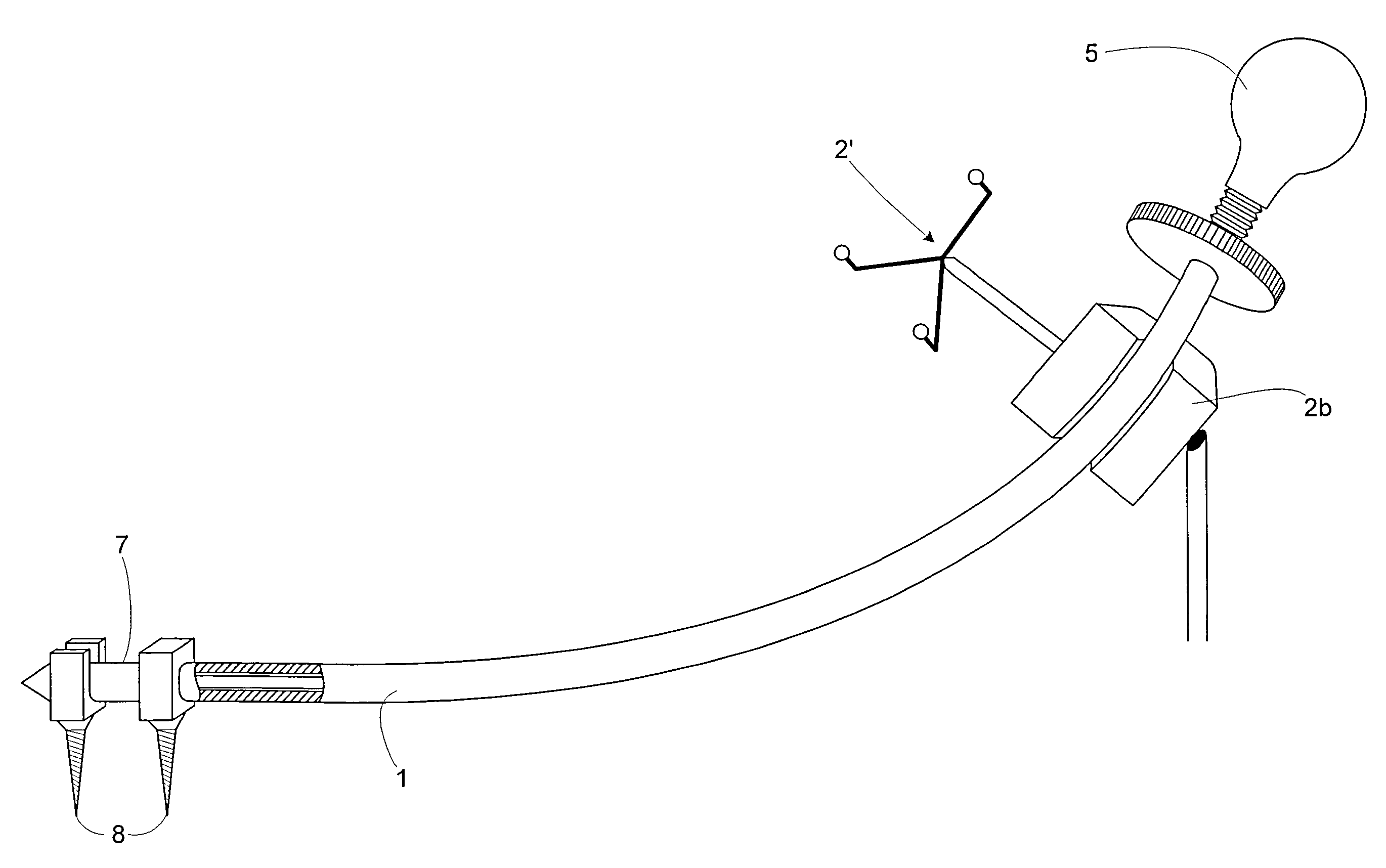
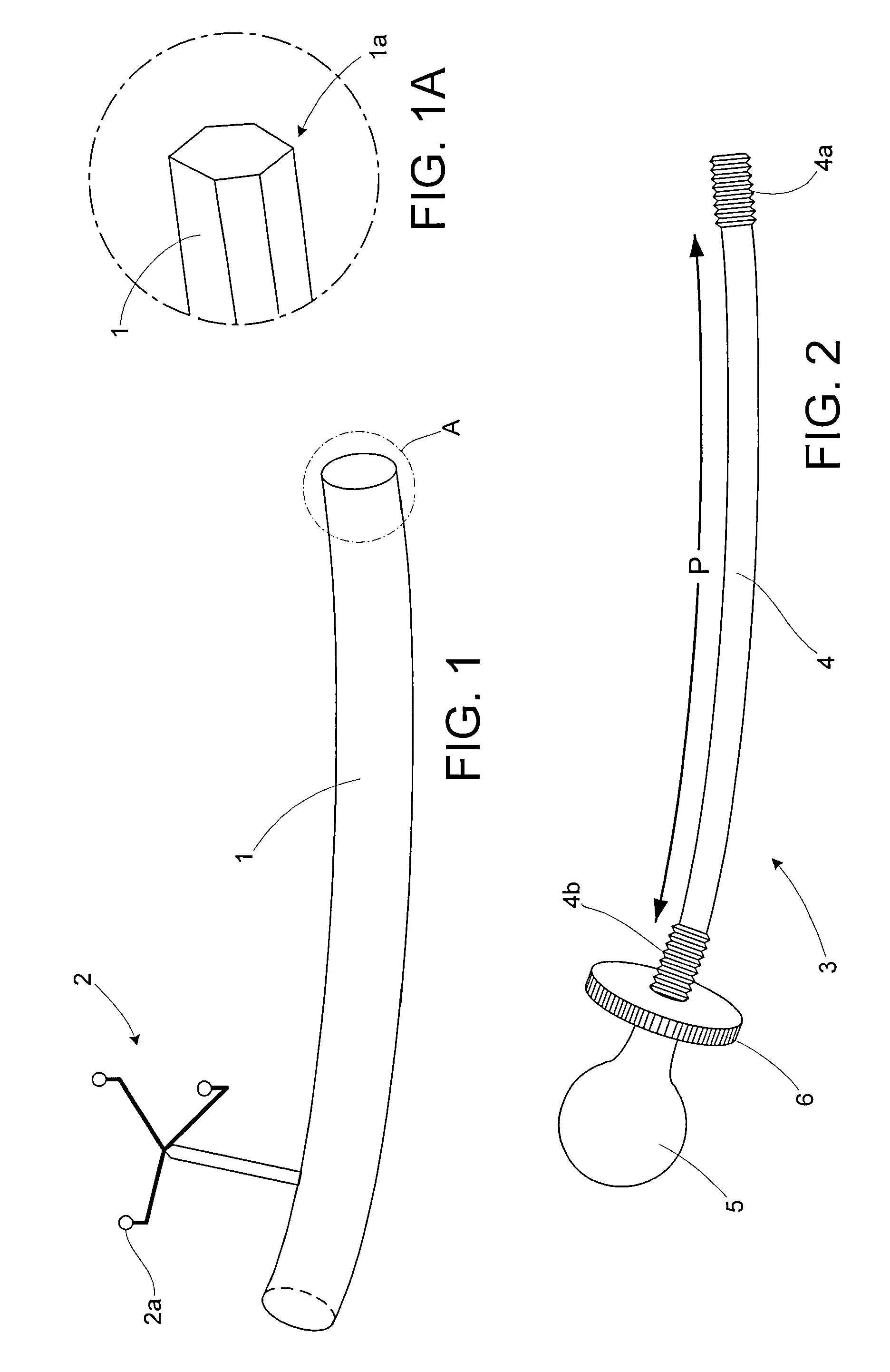
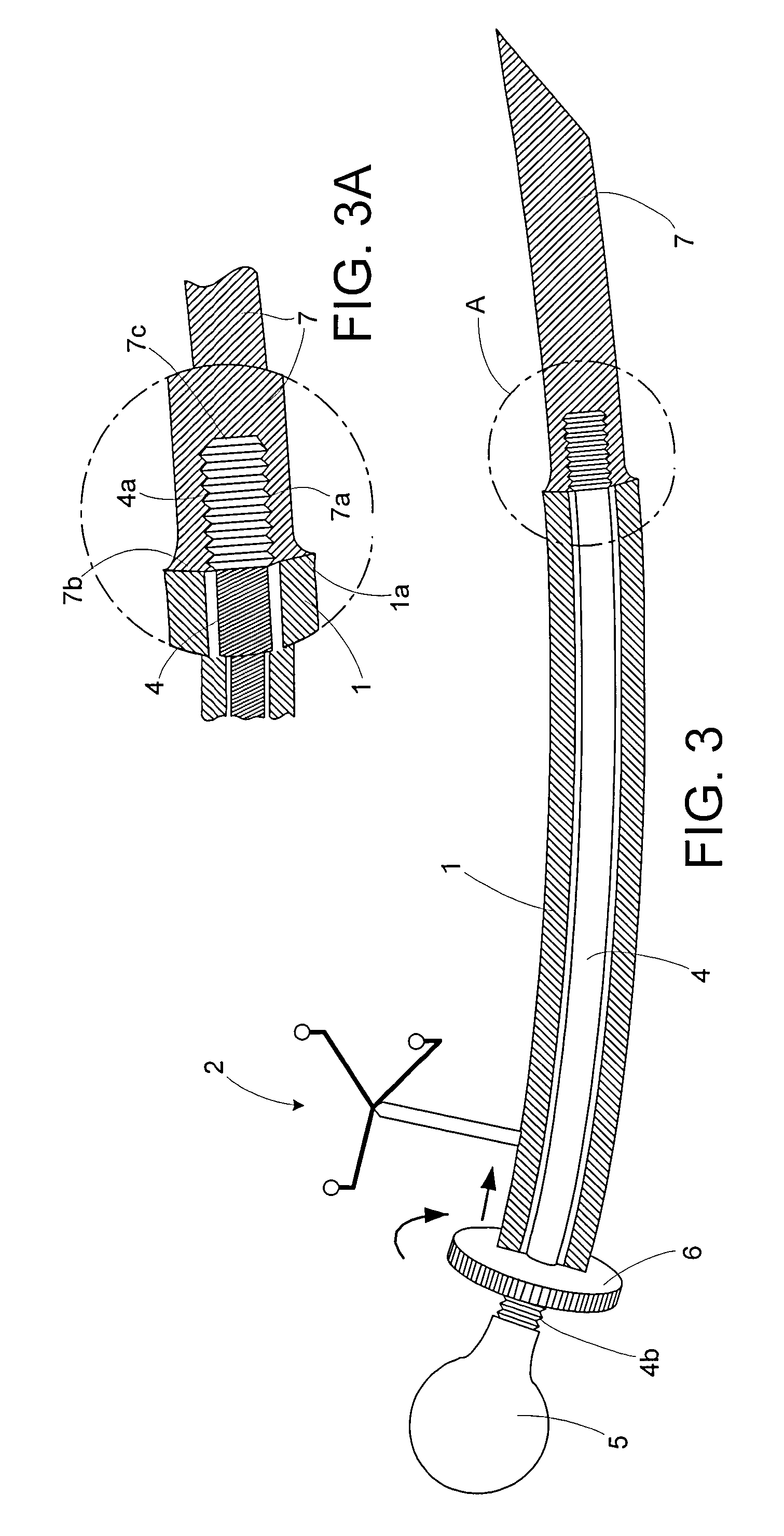
[0043]FIG. 1 shows a tubular guiding sleeve 1, which is connected to a reference star 2 (also referred to as a navigation star) including three passive markers 2a. The guiding sleeve 1 is open at its rear end, (shown on the left in FIG. 1), and at its front end, (shown on the right in FIG. 1). FIG. 1A shows a cross-section of the part of the guiding sleeve 1 indicated by A in FIG. 1, in an enlarged representation. As shown in FIG. 1A, the guiding sleeve 1 includes a rim area 1a which runs broadly conically, onto which an implant 7 can be placed, as shown in FIG. 3.

[0044]FIG. 2 shows a holding element 3. The holding element 3 can include an elastic or otherwise flexible section 4 (shown by the arrows P). The section 4 can, for example, be a flexible metal or plastic element having an outer thread 4a in its front end, (shown on the right in FIG. 2). The rear end of the flexible section or area 4, (shown on the left in FIG. 2), likewise can include an outer thread 4b, onto which a nut ...


PUM


Abstract

A system for positioning an implant includes a holding element for holding an implant. The holding element can include a first end having a grip and a second end having a connecting element for establishing a connection to the implant. The system includes a guiding sleeve for guiding the holding element. The guiding sleeve defines a guiding area for guiding the holding element, where the holding element can be introduced into the guiding sleeve and a method for calibrating an element includes connecting the element to at least one navigation element and placing the element in contact with a calibrating device. The element is moved while the element remains in contact with the calibrating device. A device for calibrating an element includes a planar member connected to at least one navigation element.

Description

RELATED APPLICATION DATA[0001]This application claims priority of U.S. Provisional Application No. 60 / 440,703, filed on Jan. 17, 2003 and of U.S. Provisional Application No. 60 / 440,707, filed on Jan. 13, 2003, which are incorporated herein by reference in their entirety.FIELD OF THE INVENTION[0002]The present invention relates generally to a device for inserting an element, such as a rod, into a body in a minimally invasive way. The invention further relates generally to a method for calibrating an element, such as a curved implant or instrument, which can be used in operations in the area of the spine.BACKGROUND OF THE INVENTION[0003]During surgery or operations in the area of the spine, such as operations involving attaching pedical screws to individual vertebrae and fixing rods between pedical screws on adjacent vertebrae, the entire area of the spine to be operated on is exposed. First, the pedical screws are inserted into the exposed vertebrae, then each rod is placed between t...

Claims


Application Information

Patent Timeline
Patent Type & Authority Patents(United States)
IPC IPC(8): A61B17/88A61B17/00A61B17/34A61B19/00
CPCA61B17/7083A61B19/52A61B19/5244A61B17/3421A61B19/46A61B2017/0046A61B2017/00725A61B2019/507A61B2019/5255A61B2019/527A61B2019/5483A61B2090/3983A61B90/36A61B2034/2055A61B2034/207A61B34/20A61B90/06A61B2034/107
Inventor BLAU, ARNOSEIFFERTH, FALKOZEISS, MARIO
Owner BRAINLAB
Why Eureka
Try Eureka