Pulse-generator circuit and circuit arrangement

a generator circuit and circuit technology, applied in the direction of pulse generators, pulse techniques, electrical apparatus, etc., can solve the problems of circuit arrangements with pulse generator circuits, parasitic capacitances, and insufficient switching speed for many applications, and achieve the effect of reducing the number of circuit arrangements

Inactive Publication Date: 2010-07-27
INFINEON TECH AG
View PDF10 Cites 10 Cited by
  • Summary
  • Abstract
  • Description
  • Claims
  • Application Information

AI Technical Summary

Problems solved by technology

In an implementation with modem sub-100 nm or CMOS technologies, it is apparent, however, that the parasitic capacitances of the MOS transistors form a part of the total capacitance to be driven which is not negligible.
In summary, the circuit arrangements with pulse generator circuits, known from the prior art, are not sufficiently fast with respect to the switching speed for many applications.

Method used


Image

  • Pulse-generator circuit and circuit arrangement
  • Pulse-generator circuit and circuit arrangement
  • Pulse-generator circuit and circuit arrangement

Examples


Embodiment Construction

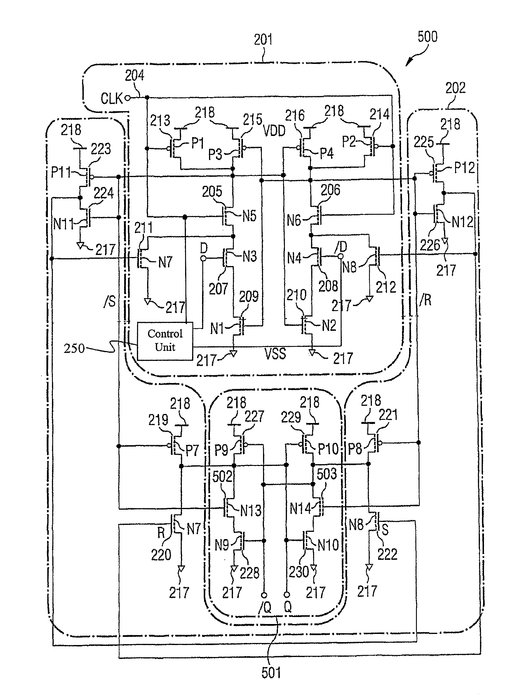
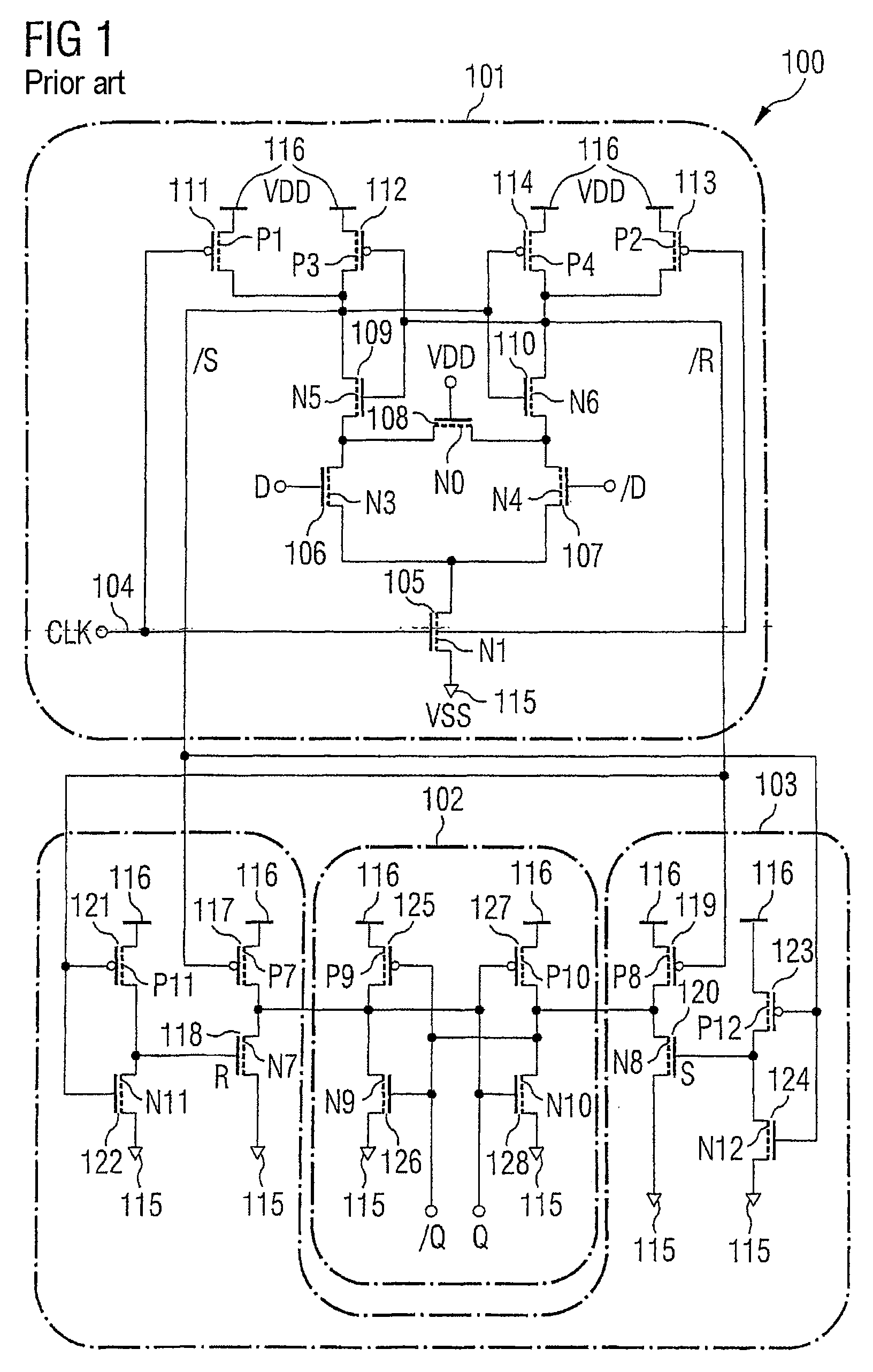
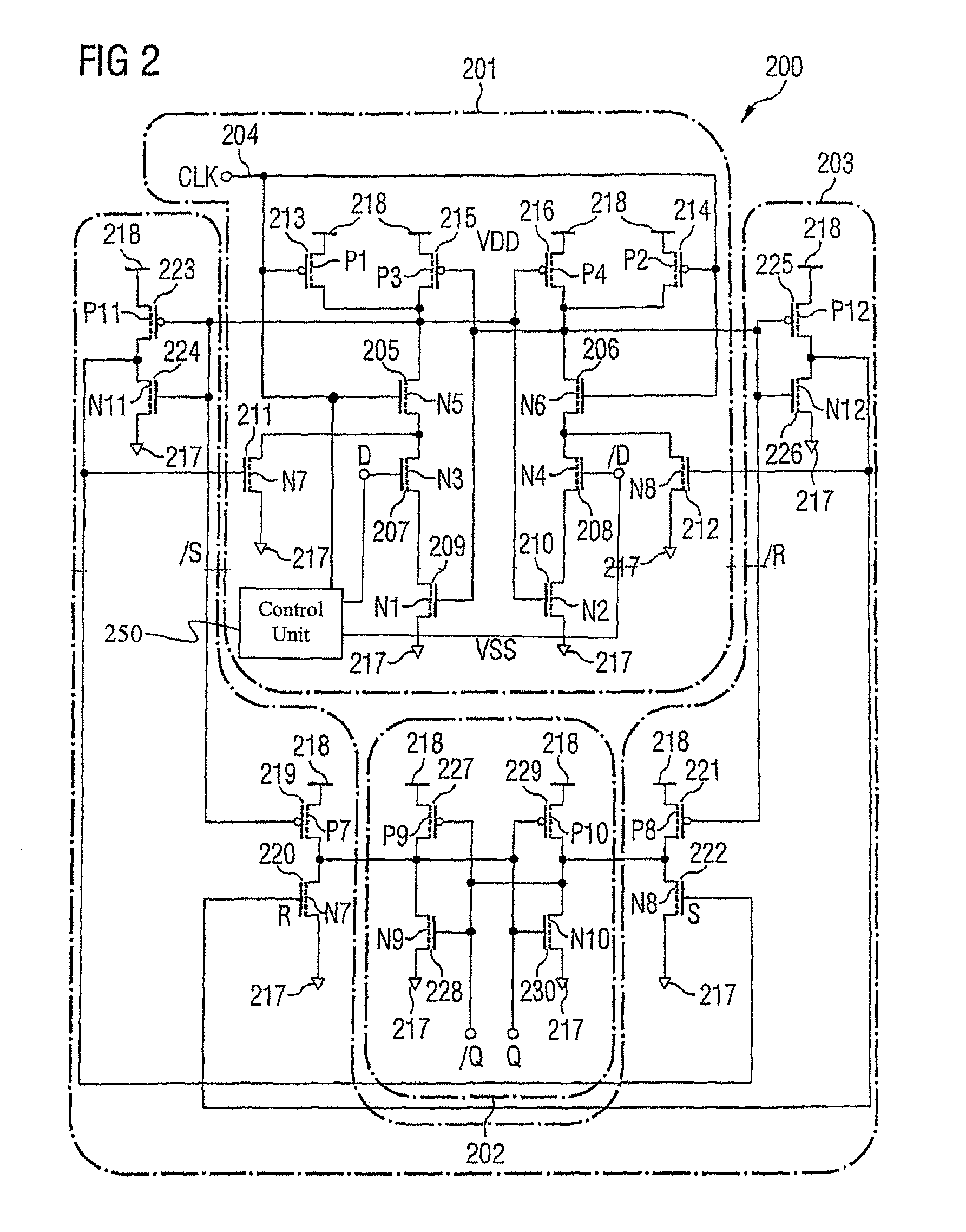
[0038]A basic concept of the invention can be seen in the fact that, in a pulse generator circuit for generating an input signal for a flip flop circuit from a clock signal and from a data signal, a cascade of clock pulse field effect transistor, logic field effect transistor and feedback field effect transistor is interconnected in a manner modified compared with the prior art, in such a manner that an increased signal processing speed is achieved when a signal passes through the three transistors. This increase in speed is based on the fact that, for generating the input signal, the clock pulse field effect transistor arranged last or right at the end in the cascade with regard to the signal flow (i.e. the one at the terminal of which the input signal is generated) is chronologically activated only when the logic field effect transistor and the feedback field effect transistor have already been activated or switched for generating the flip flop signal.

[0039]In other words, accordi...


PUM


Abstract

Pulse-generator circuit for generating an input signal for a flip-flop circuit from a clock-pulse signal and a data signal. The circuit includes a control unit for controlling a clock-pulse field effect transistor, a logic field effect transistor and a feedback field effect transistor. To generate the input signal, the control unit is configured in such a way that the clock-pulse field effect transistor is controlled chronologically after the logic field effect transistor and the feedback field effect transistor, thus generating the flip-flop signal.

Description

CROSS-REFERENCE TO RELATED APPLICATION[0001]This application is a nation stage of International Patent Application Serial No. PCT / DE2005 / 000263, filed Feb. 16, 2005, which published in German on Sep. 22, 2005 as WO 2005 / 088837, and is incorporated herein by reference in its entirety.FIELD OF THE INVENTION[0002]The invention relates to a pulse generator circuit and to a circuit arrangement.BACKGROUND OF THE INVENTION[0003]Edge-controlled flip flops or edge-controlled master / slave latch pairs are essential basic building blocks for synchronizing multi-stage logic circuits. They are used in almost all modem integrated digital circuits such as digital signal processors (DSPs), microprocessors and integrated circuits for communication applications for increasing the data flow by means of pipelining. For applications with low active power dissipation, flip flops and master / slave latch pairs must still operate reliably and have sufficient switching speed when the difference between a suppl...

Claims


Application Information

Patent Timeline
Patent Type & Authority Patents(United States)
IPC IPC(8): H03K3/356
CPCH03K3/356121
Inventor PACHA, CHRISTIANVON ARNIM, KLAUS
Owner INFINEON TECH AG
Why Eureka
Try Eureka