Auto-correction feedback loop for offset and ripple suppression in a chopper-stabilized amplifier

a chopper-stabilized amplifier and feedback loop technology, applied in the direction of pulse technique, amplifier with semiconductor devices/discharge tubes, electronic switching, etc., can solve the problems of increased in-band noise, ripple at the chopping frequency appearing in the output voltage, and the effect of increasing the in-band nois

Active Publication Date: 2010-07-27
ANALOG DEVICES INC
View PDF9 Cites 126 Cited by
  • Summary
  • Abstract
  • Description
  • Claims
  • Application Information

AI Technical Summary

Benefits of technology

[0010]A chopper-stabilized amplifier with an auto-correction feedback loop is presented which overcomes a number of the problems described above, in that the feedback loop operates to suppress both input offset voltage effects and offset voltage-induced ripple that would otherwise appear in the amplifier's output.
[0012]The auto-correction feedback loop includes a third transconductance amplifier which is preferably connected to receive the chopped first differential output at its input and which produces a third differential output in response, a third chopping circuit which chops the third differential output in response to the chopping clock, a filter arranged to filter the chopped third differential output so as to substantially reduce any offset voltage-induced AC component present in the signal, and a fourth transconductance amplifier which receives the filtered output at its input and produces a fourth differential output in response. The fourth differential output is the output of the feedback loop, and is coupled to the first differential output, and thereby into the main signal path. When properly arranged, the auto-correction feedback loop operates to suppress transconductance amplifier-related offset voltages and offset voltage-induced ripple that might otherwise be present in the amplifier's output.

Problems solved by technology

However, both of these techniques have drawbacks.
For example, auto-zeroing can result in increased in-band noise due to aliasing, whereas chopper-stabilizing can result in ripple at the chopping frequency appearing in the output voltage.
However, the S / H circuit adds an additional pole to the amplifier's frequency response, and makes frequency compensation difficult.
However, no means is provided to suppress an input offset voltage associated with the loop's feedback amplifier.

Method used


Image

  • Auto-correction feedback loop for offset and ripple suppression in a chopper-stabilized amplifier
  • Auto-correction feedback loop for offset and ripple suppression in a chopper-stabilized amplifier
  • Auto-correction feedback loop for offset and ripple suppression in a chopper-stabilized amplifier

Examples


Embodiment Construction

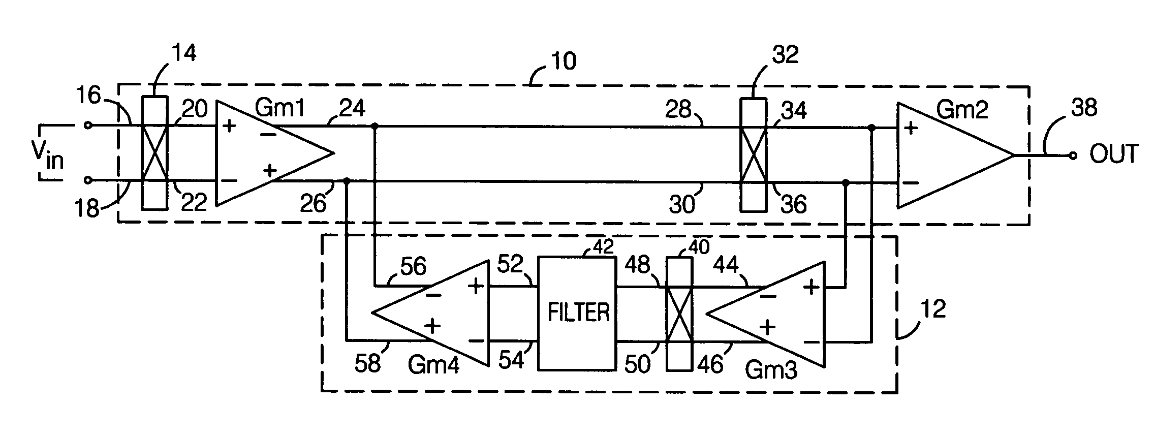
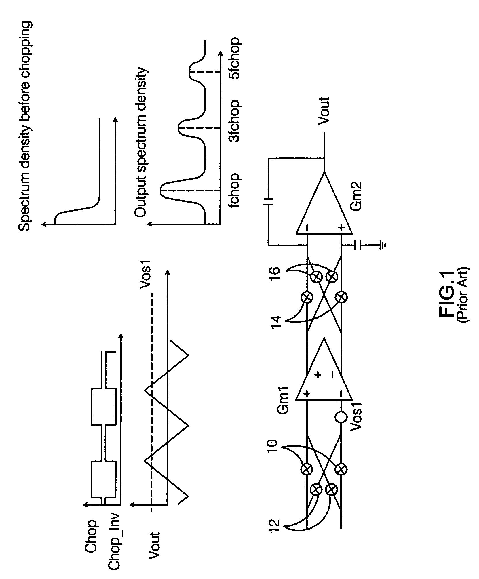
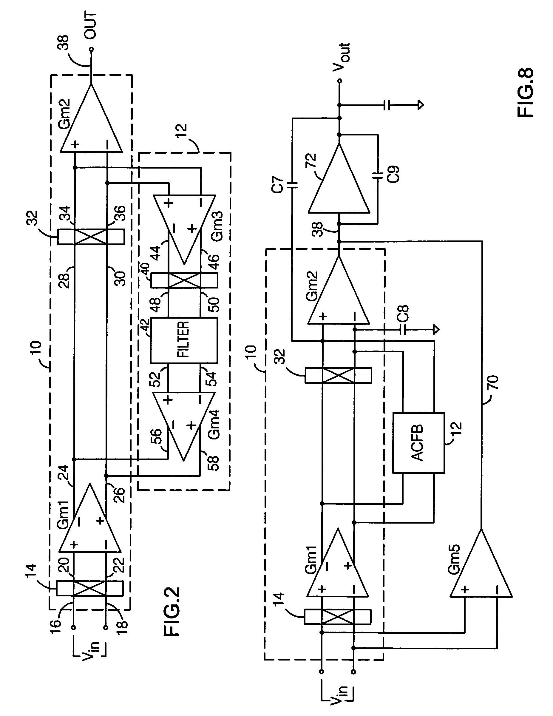
[0024]The present chopper-stabilized amplifier employs a novel auto-correction feedback loop, which operates to suppress transconductance amplifier-related offset voltages and offset voltage-induced ripple that might otherwise appear in the amplifier's output. A block / schematic diagram of one possible embodiment is shown in FIG. 2. The amplifier includes a main signal path 10 and an auto-correction feedback loop 12. The main signal path includes an input chopping circuit 14 which receives a differential input signal Vin. Chopping circuit 14, and all other chopping circuits described herein, operate in the same manner: during a first phase of a two-phase chopping clock, input terminals 16 and 18 are connected to output terminals 20 and 22, respectively; during the second clock phase, input terminals 16 and 18 are connected to output terminals 22 and 20, respectively. Chopping circuits such as chopping circuit 14 are typically made from four switches as illustrated in FIG. 1; the symb...


PUM


Abstract

A chopper-stabilized amplifier includes a main signal path having first and second chopping circuits at the inputs and outputs of a transconductance amplifier, and an auto-correction feedback loop. The feedback loop includes a transconductance amplifier connected to amplify the chopped output from the main signal path, a third chopping circuit which chops the amplified output, a filter which filters the chopped output to substantially reduce any offset voltage-induced AC component present in the signal being filtered, and a transconductance amplifier which receives the filtered output and produces an output which is coupled back into the main signal path. When properly arranged, the auto-correction feedback loop operates to suppress transconductance amplifier-related offset voltages and offset voltage-induced ripple that might otherwise be present in the amplifier's output.

Description

RELATED APPLICATIONS[0001]This application claims the benefit of provisional patent application No. 61 / 191,919 to Yoshinori Kusuda and Thomas L. Botker, filed Sep. 11, 2008.BACKGROUND OF THE INVENTION[0002]1. Field of the Invention[0003]This invention relates generally to chopper-stabilized amplifiers, and more particularly, to means for reducing offset and ripple in such amplifiers.[0004]2. Description of the Related Art[0005]Operational amplifiers are ubiquitous in electronic circuitry. In some applications, it is essential that an op amp have a very low input offset voltage. Two techniques are commonly employed to achieve this: auto-zeroing and chopper-stabilizing. However, both of these techniques have drawbacks. For example, auto-zeroing can result in increased in-band noise due to aliasing, whereas chopper-stabilizing can result in ripple at the chopping frequency appearing in the output voltage.[0006]A conventional chopper-stabilized amplifier is shown in FIG. 1. A set of cho...

Claims


Application Information

Patent Timeline
Patent Type & Authority Patents(United States)
IPC IPC(8): H03F1/02
CPCH03F3/45977
Inventor KUSUDA, YOSHINORIBOTKER, THOMAS L.
Owner ANALOG DEVICES INC
Why Eureka
Try Eureka