Electronic system with a heat sink assembly

a technology of electronic systems and heat sinks, applied in the field of electronic systems, can solve problems such as circuits and electronic components of motherboards that can be damaged, motherboards to rupture,

Inactive Publication Date: 2010-07-27
FU ZHUN PRECISION IND SHENZHEN +1
View PDF5 Cites 7 Cited by
  • Summary
  • Abstract
  • Description
  • Claims
  • Application Information

AI Technical Summary

Benefits of technology

[0007]According to a preferred embodiment of the present invention, an electronic system comprises an enclosure, a printed circuit board in the enclosure, and a heat sink assembly comprising a holding member. The enclosure comprises a first panel and a second panel perpendicularly connecting with the first panel. The printed circuit board is mounted on the first panel of the enclosure. The heat sink assembly has a first end mounted on the printed circuit board for contacting a heat-generating electronic device on the printed circuit board, and a second end opposite to the first end. The holding member connects the second panel of the enclosure with the second end of the heat sink assembly, thereby to fasten the second end of the heat sink assembly to the enclosure. Accordingly, the first end and the opposite second end of the heat sink assembly are both supported by the enclosure to prevent a too large shearing force generated by a weight the of heat sink assembly from acting on the printed circuit board.

Problems solved by technology

The large shearing force can possibly cause the motherboard to rupture; when this happens, circuits and electronic components of the motherboard can be damaged.

Method used


Image

  • Electronic system with a heat sink assembly
  • Electronic system with a heat sink assembly
  • Electronic system with a heat sink assembly

Examples


Embodiment Construction

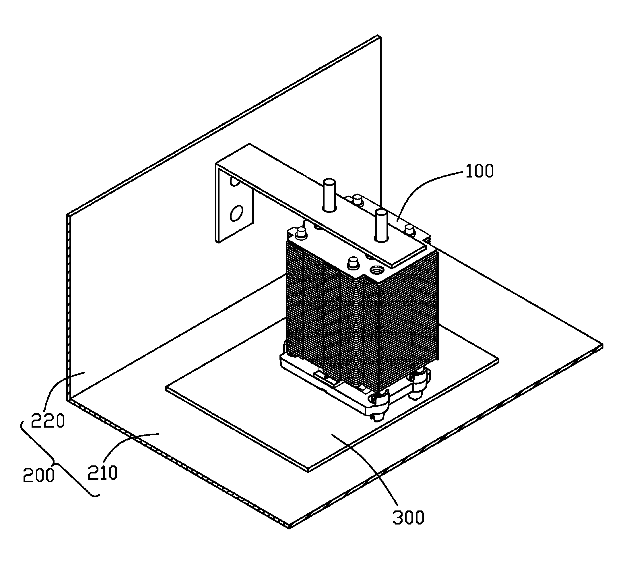
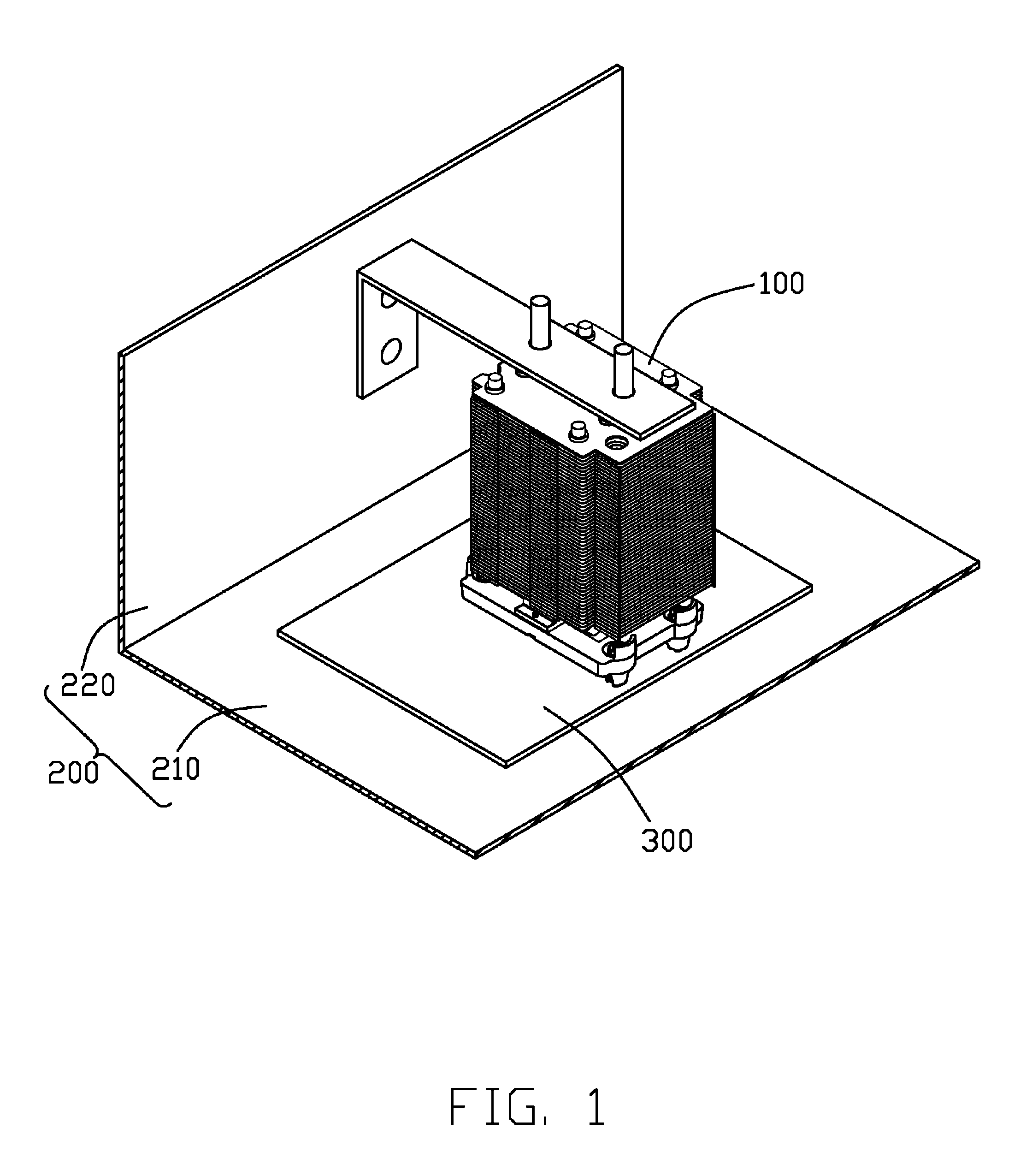
[0012]FIG. 1 shows an electronic system in accordance with a preferred embodiment of the present invention. The electronic system comprises an enclosure 200, a printed circuit board (PCB) 300 secured in the enclosure 200, and a heat sink assembly 100 mounted on the PCB 300. The enclosure 200 comprises a first panel 210 and a second panel 220 perpendicularly connecting with the first panel 210. The PCB 300 is mounted to the first panel 210 in a parallel manner.

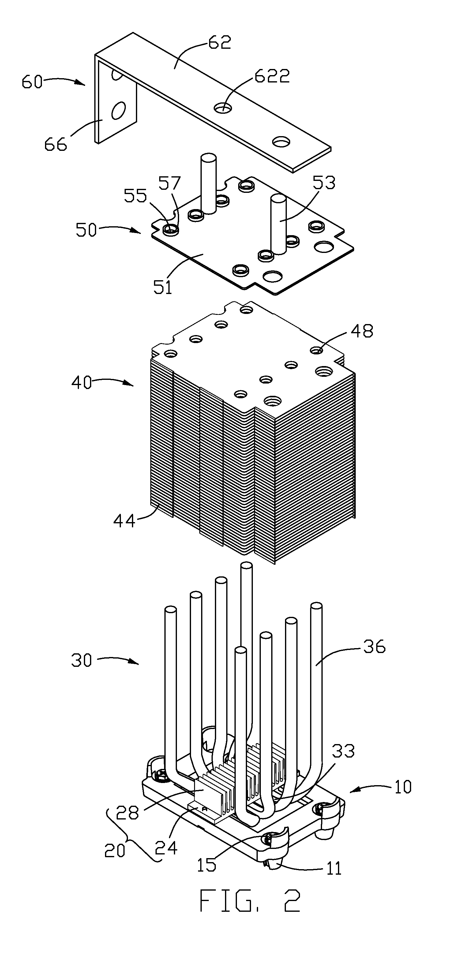
[0013]Also referring to FIG. 2 and FIG. 3, the heat sink assembly 100 comprises a heat spreader 10, a heat sink 20 with a plurality of first fins 28, a plurality of second fins 40, and four U-shaped heat pipes 30 thermally connecting the heat spreader 10 with the heat sink 20 and the second fins 40. The heat sink assembly 100 further comprises a connecting member 50 for connecting with the heat pipes 30 at a position remote from the heat spreader 10. A holding member 60 is for connecting the connecting member 50 with the second...


PUM


Abstract

An electronic system comprises an enclosure, a printed circuit board in the enclosure, and a heat sink assembly comprising a holding member. The enclosure comprises a first panel and a second panel perpendicularly connecting with the first panel. The printed circuit board is mounted on the first panel of the enclosure. The heat sink assembly has a first end mounted on the printed circuit board for contacting a heat-generating electronic device on the printed circuit board, and a second end opposite to the first end. The holding member connects the second panel of the enclosure with the second end of the heat sink assembly.

Description

BACKGROUND OF THE INVENTION[0001]1. Field of the Invention[0002]The present invention relates to an electronic system, and more particularly to an electronic system with a heat sink assembly.[0003]2. Description of Related Art[0004]It is well known that heat is produced during operation of electronic devices such as central processing units (CPUs) mounted on a printed circuit board such as a motherboard in a computer enclosure. The heat produced must be quickly removed to ensure normal operation of the electronic device. Typically, a heat sink assembly is used to remove the heat from the electronic device.[0005]Conventionally, a heat sink assembly in an electronic system comprises a heat sink and a locking device for securing the heat sink to an electronic device mounted on a motherboard located in an enclosure of the electronic system. Generally, the motherboard is vertical in the enclosure. The heat sink is perpendicular to the motherboard and oriented horizontally. An end of the ...

Claims


Application Information

Patent Timeline
Patent Type & Authority Patents(United States)
IPC IPC(8): H05K7/20F28F7/00H01L23/34
CPCH01L23/427H01L23/467H01L23/3672H01L2924/0002H01L2924/00
Inventor LI, DONG-YUNWU, WEIYU, JIAN-PING
Owner FU ZHUN PRECISION IND SHENZHEN
Why Eureka
Try Eureka