Direct metal deposition apparatus utilizing rapid-response diode laser source

a laser source and diode technology, applied in the field of additive manufacturing, to achieve the effect of enhancing dimensional control and capability, fast response time, and fast response tim

Inactive Publication Date: 2010-07-27
DM3D TECH
View PDF14 Cites 58 Cited by
  • Summary
  • Abstract
  • Description
  • Claims
  • Application Information

AI Technical Summary

Benefits of technology

[0010]Broadly, this invention incorporates one or more diode lasers for the high-power CO2 or Nd-YAG lasers currently used in closed-loop DMD systems. Being semiconductor-based, such devices are almost instantaneously responsive to the electrical input. As such, a DMD sy

Problems solved by technology

However, previous approaches are all open-loop processes requiring either a considerable

Method used


Image

  • Direct metal deposition apparatus utilizing rapid-response diode laser source
  • Direct metal deposition apparatus utilizing rapid-response diode laser source
  • Direct metal deposition apparatus utilizing rapid-response diode laser source

Examples


Embodiment Construction

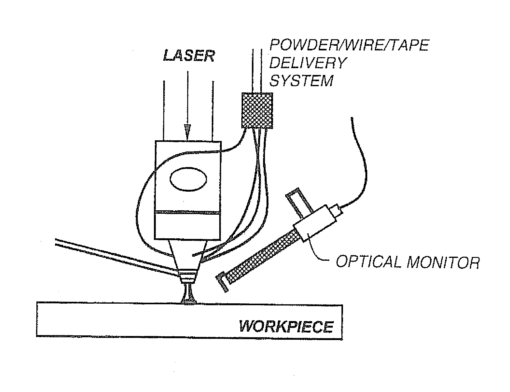
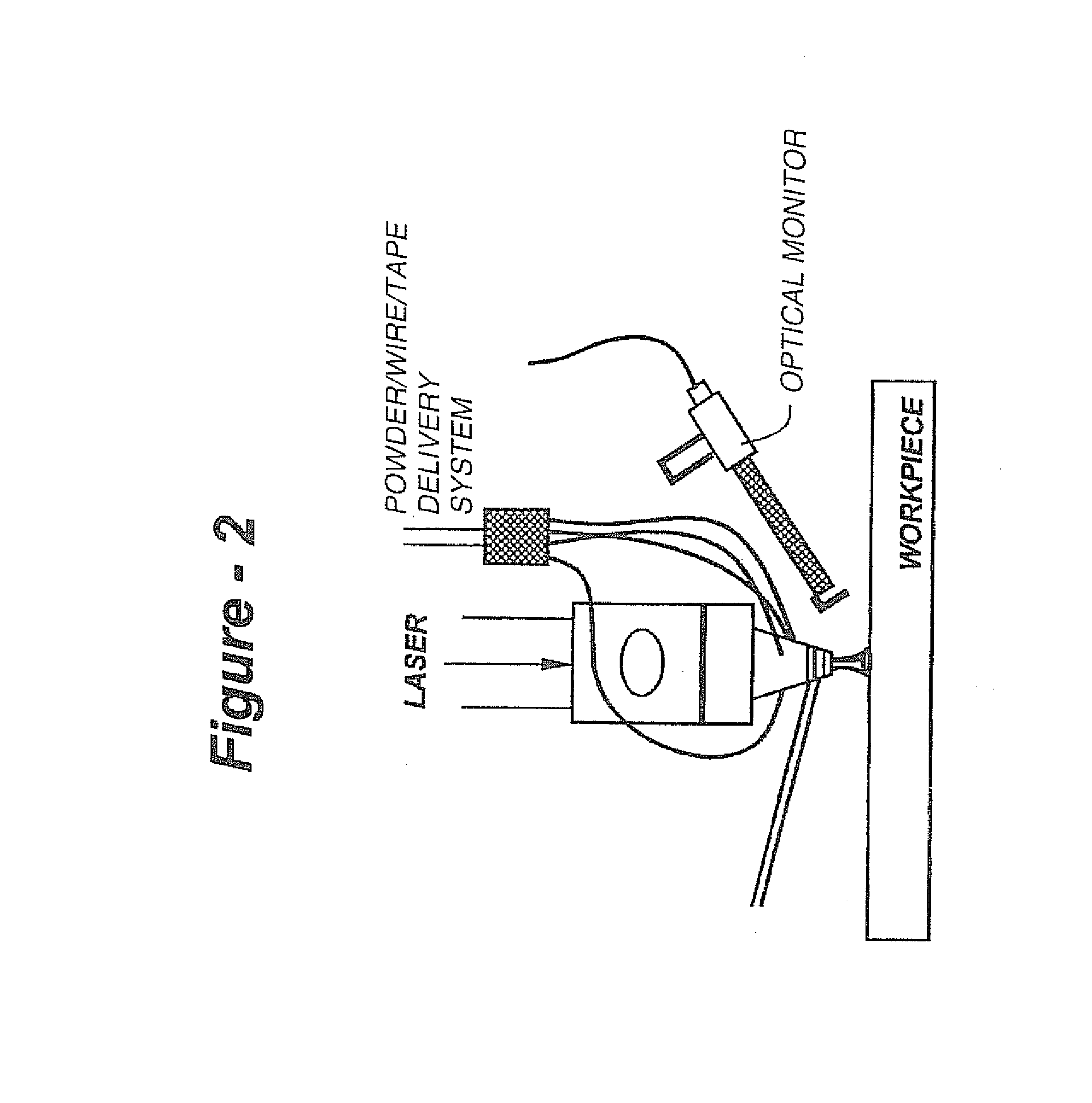
[0017]As described in U.S. Pat. No. 6,122,564, the entire contents of which are incorporated herein by reference, a closed-loop direct metal deposition (DMD™) process may be employed to fabricate three-dimensional components utilizing the tool path generated by a suitably equipped CAD / CAM package. A complex shape is generated by delivering desired material (i.e., metal / alloy powder or wire) to a laser-melted pool, with a finished part being created by changing the relative position of the laser beam and the substrate. The system may use a stationary beam and material delivery system in conjunction with a moving substrate, or the beam and material delivery system may be moved relative to a stationary substrate.

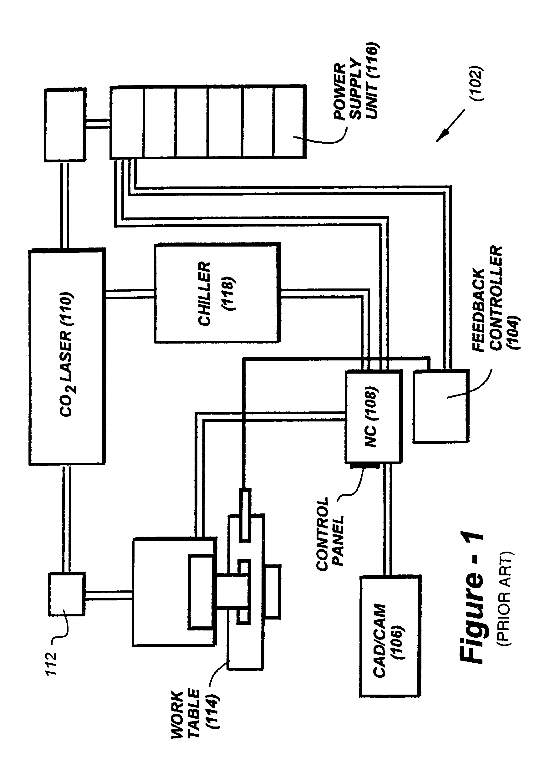
[0018]FIG. 1 shows a laser-aided, computer-controlled DMD system schematically at 102 being used to apply layers of material on a substrate to fabricate an object or cladding. The system is preferably equipped with feedback monitoring, better seen in FIG. 2, to control of the d...


PUM

PropertyMeasurementUnit
Frequencyaaaaaaaaaa
Responsivityaaaaaaaaaa

Abstract

The present invention incorporates one or more diode lasers for the high-power CO2 or Nd-YAG lasers currently used in closed-loop DMD systems. Being semiconductor-based, such devices are almost instantaneously responsive to the electrical input. As such, a DMD system driven by a diode laser according to the invention provides a much faster response compared to other sources. The faster response time, in turn, provides for enhanced dimensional control and capability to produce intricate components with better dimensional accuracy.

Description

REFERENCE TO RELATED APPLICATIONS[0001]This application claims priority of U.S. Provisional patent application Ser. No. 60 / 221,250, filed Jul. 27, 2000, and is a continuation-in-part of U.S. patent application Ser. Nos. 09 / 526,631, filed Mar. 16, 2000 now U.S. Pat. No. 6,937,921; 09 / 570,986, filed May 15, 2000 now U.S. Pat. No. 6,410,105; and 09 / 608,874, filed Jun. 30, 2000 now U.S. Pat. No. 7,286,893, which is a continuation-in-part of U.S. patent application Ser. No. 09 / 107,912, filed Jun. 30, 1998, now U.S. Pat. No. 6,122,564, the entire contents of each application being incorporated herein by reference.FIELD OF THE INVENTION[0002]This invention relates generally to additive manufacturing and, in particular, to a direct metal deposition (DMD™) system utilizing a rapid-response diode laser source.BACKGROUND OF THE INVENTION[0003]Fabrication of three-dimensional metallic components via layer-by-layer laser cladding was first reported in 1978 by Breinan and Kear. In 1982, U.S. Pat....

Claims


Application Information

Patent Timeline
IPC IPC(8): G06F19/00B23K26/03B23K26/34C23C4/12
CPCB23K26/032B23K26/3206C23C4/12B23K26/34B23K26/32B23K2103/50B33Y40/00B33Y10/00
Inventor MAZUMDER, JYOTIMORGAN, DWIGHTSKSZEK, TIMOTHY W.LOWNEY, MATTHEW
Owner DM3D TECH
Why Eureka
Try Eureka