Ultrasound diagnostic apparatus, program for imaging an ultrasonogram, and method for imaging an ultrasonogram

a diagnostic apparatus and ultrasonogram technology, applied in the field of ultrasonogram imaging technology, can solve problems such as measurement value errors due to displacement, and achieve the effect of improving the measurement accuracy of living tissue displacemen

Inactive Publication Date: 2010-08-03
HITACHI MEDICAL CORP
View PDF9 Cites 14 Cited by
  • Summary
  • Abstract
  • Description
  • Claims
  • Application Information

AI Technical Summary

Benefits of technology

[0006]It is an object of the present invention to provide an ultrasound diagnostic apparatus, program for imaging an ultrasonogram, and method for imaging an ultrasonogram that are suitable to take an elasticity image precisely indicating characteristics of the living tissue by improving measurement precision of the displacement of the living tissue.
[0008]According to a preferable aspect of the present invention, even if the displacement search direction does not match the tissue displacement direction, the displacement search direction can match the tissue displacement direction. The displacement of the tissue is measured in the displacement search direction, thereby measuring the displacement in the direction for actually displacing the tissue. As a consequence, the precision of a measurement value is improved. The elasticity image is constructured on the basis of the measurement value, thereby reducing artifact caused in the elasticity image. Thus, the elasticity image is obtained with high quality for precisely indicating the characteristics such as the strain or hardness of the tissue.

Problems solved by technology

In this case, there is concern that a measurement value includes an error due to the displacement.

Method used


Image

  • Ultrasound diagnostic apparatus, program for imaging an ultrasonogram, and method for imaging an ultrasonogram
  • Ultrasound diagnostic apparatus, program for imaging an ultrasonogram, and method for imaging an ultrasonogram
  • Ultrasound diagnostic apparatus, program for imaging an ultrasonogram, and method for imaging an ultrasonogram

Examples


first embodiment

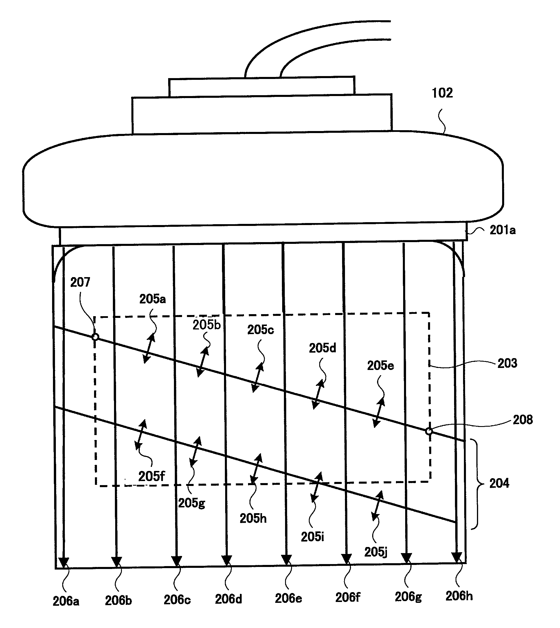
[0046]The first embodiment shows an example in which the tissue displacement direction is semi-automatically determined and ultrasound beams are deflected in the displacement search direction set to match the tissue displacement direction. FIG. 3 is a schematic diagram showing a form in which the displacement search direction does not match the tissue displacement direction. FIG. 4 is a schematic diagram showing a form in which the displacement search direction matches the tissue displacement direction.

[0047]Referring to FIG. 3, an ultrasound transmitting and receiving surface 201a of the probe 102 comes into contact with, e.g., the body surface of the subject 101. Herein, displacement search directions 206a to 206h are initialized in the ultrasound beam direction sent and received from / to the probe 102, that is, substantially in the vertical direction of the ultrasound transmitting and receiving surface 201a. Further, a vascular vessel (blood vessel) 204 in the subject 101 linearly...

second embodiment

[0062]The second embodiment is different from the first embodiment in which the ultrasound beams are deflected in that the elasticity calculating direction predetermined within the region of interest, i.e., only the displacement search direction within the region of interest matches the tissue displacement direction when the displacement search direction matches the tissue displacement direction. Therefore, the different points will be mainly described.

[0063]FIG. 7 is a diagram for illustrating the operation of the setting means 113B of the displacement search direction according to the second embodiment. An example shown in FIG. 7 is different from that shown in FIG. 4 in that the emission direction of ultrasound beams is vertical to an ultrasound transmitting and receiving surface 201a.

[0064]Upon imaging the elasticity image of the tissue of the subject 101, the ultrasound transmitting and receiving unit 103 first transmits and receives the ultrasound beams in the vertical direct...

third embodiment

[0066]The third embodiment is different from the first embodiment with the structure for automatically detecting the tissue displacement direction in that the tissue displacement direction is automatically detected. Therefore, the different points will be mainly described.

[0067]FIG. 8 is a conceptual diagram showing an example of the operation of the detecting means 113C of the tissue displacement direction shown in FIG. 2. The abscissa in FIG. 8 denotes the coordinate of the subject substantially in parallel with the ultrasound transmitting and receiving surface 201a, and the ordinate denotes the coordinate of the subject substantially in the vertical direction of the ultrasound transmitting and receiving surface 201a. The units of the abscissa and the ordinate are millimeter (mm).

[0068]Referring to FIG. 8, the detecting means 113C of the tissue displacement direction executes the correlation calculation of the tomographic images after / before applying pressure to the tissue within ...


PUM


Abstract

An ultrasound diagnostic apparatus includes a probe 102 that transmits and receives ultrasound waves to / from a subject, transmitting means 120 for supplying a drive signal to the probe 102 for transmitting ultrasound waves, receiving means 122 for receiving and processing a signal output from the probe 102, a displacement calculating unit 105 for measuring displacement of a tissue according to an output signal from an ultrasound transmitting and receiving unit 103, a color DSC 108 for reconstructuring an elasticity image on the basis of the displacement of the tissue, and an image display 112 for displaying the elasticity image. Further, the ultrasound diagnostic apparatus includes setting means 113B for setting a displacement search direction that sets a search direction of the displacement to match a tissue displacement direction for displacing the tissue. The color DSC 108 constructures the elasticity image on the basis of the measurement value of the displacement search direction.

Description

TECHNICAL FIELD[0001]The present invention relates to a technology for imaging an ultrasonogram that is an elasticity image indicating characteristics such as strain or hardness of the living tissue of a subject.BACKGROUND ART[0002]An ultrasound diagnostic apparatus for imaging an ultrasonogram comprises that supplying a drive signal to an ultrasound probe for transmitting ultrasound waves to a subject, receiving a reflection echo generated from the subject to the ultrasound probe, and reconstructuring and displaying the ultrasonogram on the basis of the reflection echo output from the ultrasound probe.[0003]One of the ultrasound diagnostic apparatuses is well known to take an elasticity image indicating characteristics such as strain or hardness of a living tissue of the subject. For example, the ultrasound diagnostic apparatus captures images on time series on the living tissue upon applying pressure to the subject, measures the displacement of the living tissue with the correlati...

Claims


Application Information

Patent Timeline
Patent Type & Authority Patents(United States)
IPC IPC(8): A61B8/00
CPCA61B5/02007A61B8/0858A61B8/14A61B8/463G01S15/8977A61B8/485A61B8/488G01S7/52042A61B8/469G01S7/52063
Inventor WAKI, KOJI
Owner HITACHI MEDICAL CORP
Why Eureka
Try Eureka