Multi-electrode ion trap

a technology of electrostatic ion traps and electrodes, applied in the direction of tube electrostatic deflection, particle separator tube details, separation process, etc., can solve the problems of increasing the difficulty of achieving the required performance level, increasing the difficulty of mass production of electrode shapes to such an exacting tolerance, and increasing the difficulty of achieving the required level of performance. , to achieve the effect of improving the maintenance of isochronicity or coherence, improving the voltage, and improving the peak shap

Active Publication Date: 2010-08-03
THERMO FINNIGAN
View PDF17 Cites 24 Cited by
  • Summary
  • Abstract
  • Description
  • Claims
  • Application Information

AI Technical Summary

Benefits of technology

[0019]Measuring a characteristic of the ions, such as a peak shape in a mass spectrum, and comparing the characteristic with a known value allows the voltages applied to the electrodes to be improved such that a better trapping field may be generated.
[0024]Generally, the “proper” tuning should give similar improvement for all peak intensities over a wide mass range and, importantly, the spread of “measured characteristics” between peaks of different intensities (but similar m / z) should be minimised. The importance of such tuning is especially high in multi-electrode electrostatic traps where high dimensionality of the search space requires exceptionally effective algorithms. The present invention proposes both general and specific approaches to such tuning, starting from the above described selection criteria and down to the most appropriate electrode configurations.
[0028]Apparent improvements in peak shape may be an artifact of self-bunching rather than true improvement of the peak shape (see, for example, GB0511375.8). As noted above, it is advantageous to check improvement in peak shapes also for significantly less intense peaks in the same or a different spectrum. Such multi-parametric measurement of the one or more characteristics will provide optimal improvement.
[0029]Preferably, the method may comprise improving the voltages so as to produce a trapping field that improves maintenance of the isochronicity or coherence of the oscillating trapped ions. Loss in coherence in the orbiting ions often leads to degradation of mass spectra, particularly where measurement of an image current is used. Accordingly, optimising the trapping field helps maintain the coherence of the orbiting ions producing improved mass spectra. Where a mass spectrum is collected over a detection time, the voltages may be improved so that any drift in phase associated with loss in coherence is less than 2π during the detection time.

Problems solved by technology

More complex assemblies are known to have greater difficulties in achieving required levels of performance because of larger spreads or accumulation of tolerances and errors, as well as increasingly troublesome tuning of the trapping field.
The consequence of this is that factors such as mass accuracy (peak position), resolution, peak intensity (related to ion abundance) and so forth may be compromised, possibly to the extent of becoming unacceptable.
Mass production of the electrode shapes to such an exacting tolerance, therefore, is a challenge.
Loss in coherence in the orbiting ions often leads to degradation of mass spectra, particularly where measurement of an image current is used.

Method used


Image

  • Multi-electrode ion trap
  • Multi-electrode ion trap
  • Multi-electrode ion trap

Examples


first embodiment

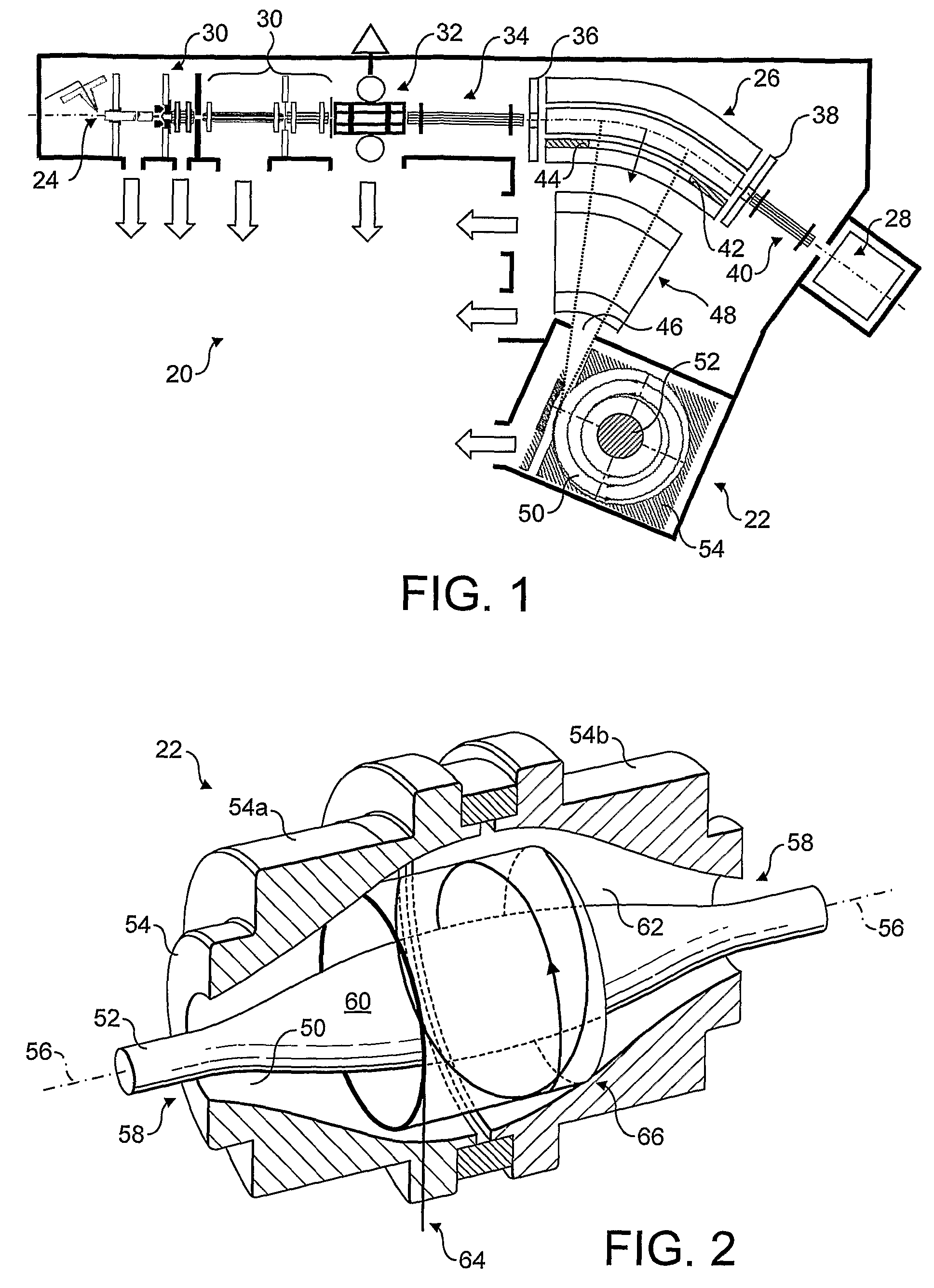
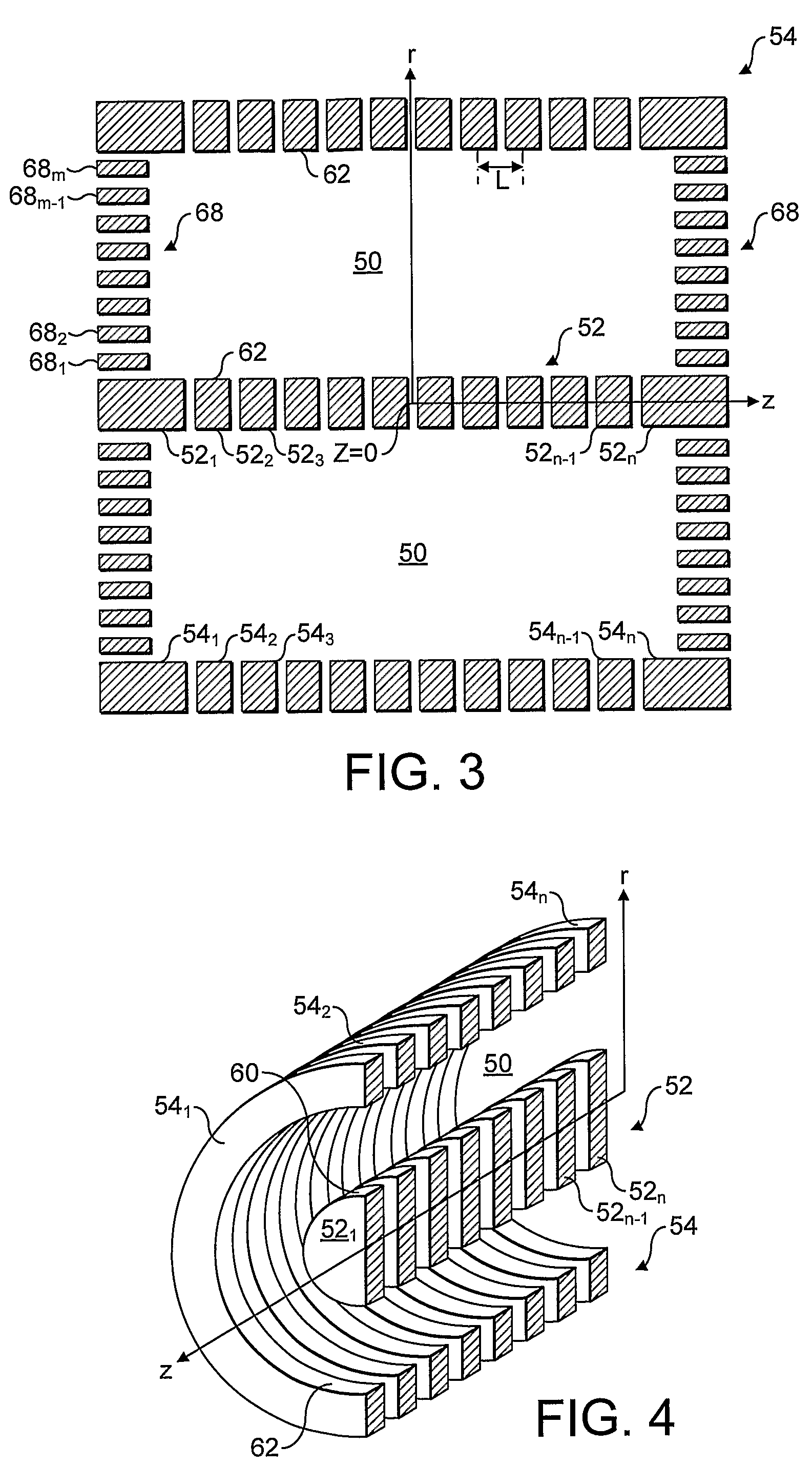
[0056]FIG. 3 corresponds to a cross-section taken along the z axis of the electrodes 52, 54 and 68 of an Orbitrap mass analyser 22 according to the present invention, and FIG. 4 shows the inner and outer electrodes 52 and 54 in perspective. In contrast to FIG. 2, the outer electrode 54 defines a cylindrical shape. The ends of the trapping volume 50 are closed by end electrodes 68 (shown only in FIG. 3), rather than being open as in FIG. 2. The inner electrode 52 is also cylindrical. Inner and outer electrodes 52 and 54 remain coaxial with the z axis.

[0057]The electrostatic mass analyser 22 of FIGS. 3 and 4 uses a quite different approach to generate the desired hyper-logarithmic field. The inner and outer electrodes 52 and 54 of FIG. 2 are shaped such that their respective outer and inner surfaces 60 and 62 follow equipotentials, thereby allowing almost the same voltage to be applied to each of the inner electrode 52 and outer electrode 54. This favoured approach of perfecting elect...

second embodiment

[0084]FIG. 8 shows the electrode structure of an Orbitrap mass analyser 22 according to the present invention. In this embodiment, there are no end electrodes 68 such that the trapping volume 50 is open at either end 58. While the inner and outer electrodes 52 and 54 still comprise sets of ring electrodes 521 . . . n and 541 . . . n, their outer and inner surfaces 60 and 62 respectively are no longer level to define cylindrical edges. Instead, the respective outer and inner surfaces 60 and 62 are staggered so as to follow approximately an equipotential of the desired hyper-logarithmic field.

[0085]Voltages may be applied to the ring electrodes 521 . . . n and 541 . . . n under computer control. As the ring electrodes 521 . . . n and 541 . . . n generally follow equipotentials, the individual voltages applied to each ring electrode 521 . . . n and 541 . . . n will be approximately equal. Thus, smaller voltages can be generated across the resistive networks 70 such that more accurate, ...

third embodiment

[0087]FIG. 9 shows an electrode arrangement in a mass analyser 22 according to the present invention. The embodiment corresponds broadly to that of FIGS. 3 and 4, except the inner electrode 52 is now formed by a single-piece electrode akin to that of the prior art of FIG. 2. It may be advantageous to use a single piece inner electrode 52 in terms of manufacturing: it is very much easier to grind or turn this inner electrode 52 as a single piece. Provision of the many ring electrodes 541 . . . n and 681 . . . m for the outer electrode 54 and end electrodes 68 means that computer control may still be used to optimise the trapping field, including correcting any inaccuracies in the shape of the inner electrode 52.


PUM


Abstract

This invention relates generally to multi-reflection electrostatic systems, and more particularly to improvements in and relating to the Orbitrap electrostatic ion trap. A method of operating an electrostatic ion trapping device having an array of electrodes operable to mimic a single electrode is proposed, the method comprising determining three or more different voltages that, when applied to respective electrodes of the plurality of electrodes, generate an electrostatic trapping field that approximates the field that would be generated by applying a voltage to the single electrode, and applying the three or more so determined voltages to the respective electrodes. Further improvements lie in measuring a plurality of features from peaks with different intensities from one or more collected mass spectra to derive characteristics, and using the measured characteristics to improve the voltages to be applied to the plurality of electrodes.

Description

FIELD OF THE INVENTION[0001]This invention relates generally to multi-reflection electrostatic systems, and more particularly to improvements in and relating to the Orbitrap electrostatic ion trap.BACKGROUND TO THE INVENTION[0002]Mass spectrometers may include an ion trap where ions are stored either during or immediately prior to mass analysis. The achievable high performance of all trapping mass spectrometers is known to depend most critically on the quality of the electromagnetic fields used in the ion trap, including non-linear components of higher orders. This quality and its reproducibility are defined, in their turn, by the degree of control over imperfections in manufacturing the ion trap and the associated power supplies that provide signals to electrodes in the ion trap to create the trapping field. More complex assemblies are known to have greater difficulties in achieving required levels of performance because of larger spreads or accumulation of tolerances and errors, a...

Claims


Application Information

Patent Timeline
Patent Type & Authority Patents(United States)
IPC IPC(8): B01D59/44H01J49/42
CPCH01J49/0009H01J49/425H01J49/282H01J49/22H01J49/0031H01J49/42H01J49/4245H01J49/424
Inventor MAKAROV, ALEXANDER ALEKSEEVICH
Owner THERMO FINNIGAN
Why Eureka
Try Eureka