Harmonic torque ripple reduction at low motor speeds

a low motor speed and torque ripple technology, applied in the direction of motor/generator/converter stopper, dynamo-electric gear control, dynamo-electric converter control, etc., can solve the problems of speed ripple, excite driveline resonance, and torque rippl

Active Publication Date: 2010-08-03
GM GLOBAL TECH OPERATIONS LLC
View PDF19 Cites 54 Cited by
  • Summary
  • Abstract
  • Description
  • Claims
  • Application Information

AI Technical Summary

Benefits of technology

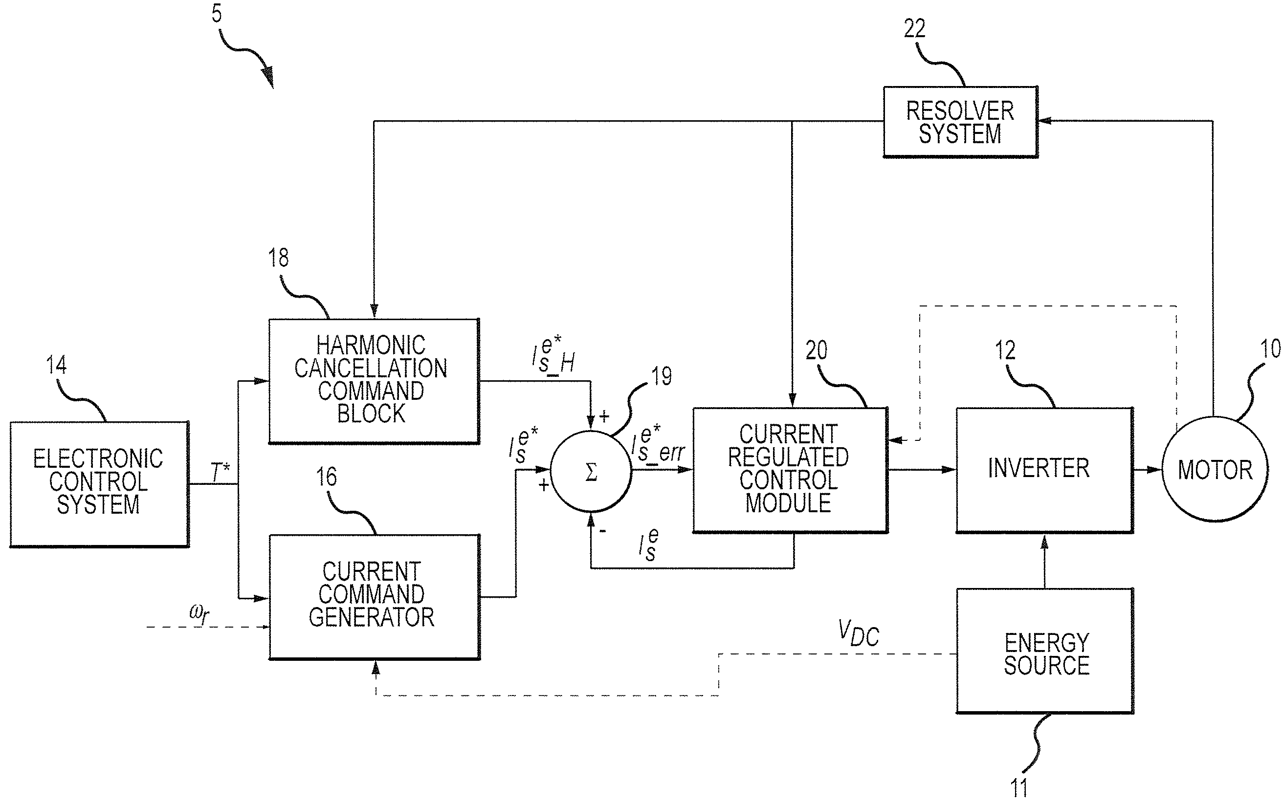
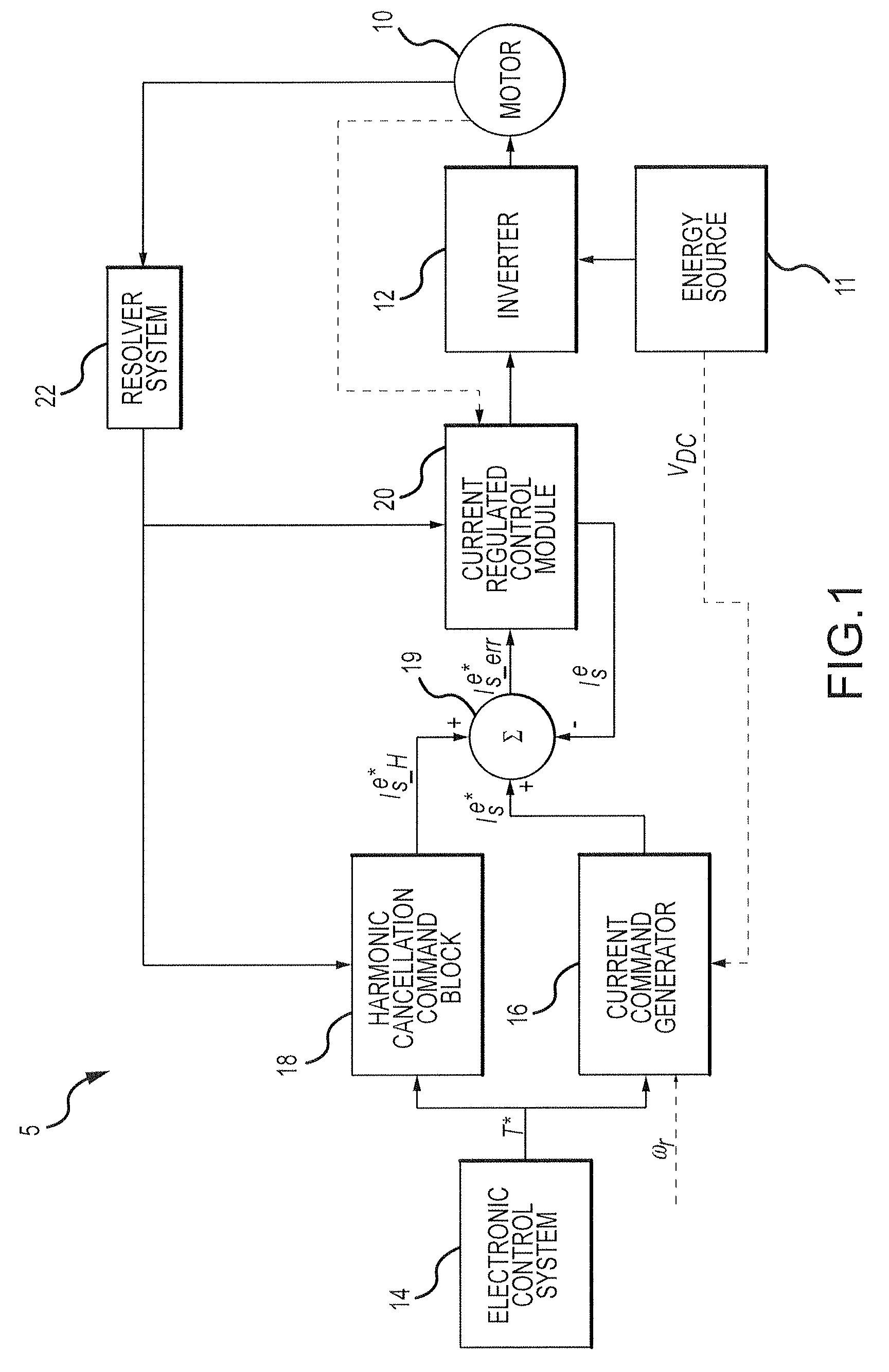
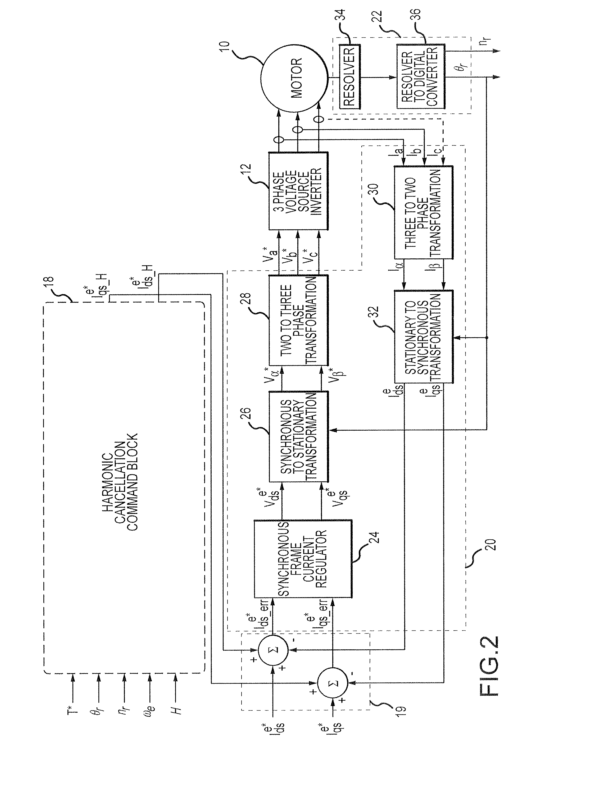
[0007]An apparatus is provided for a controller for reducing torque ripple in an electric motor in response to a torque command, wherein the electric motor is coupled to an inverter. The controller comprises a current regulated control module, wherein the current regulated control module generates control signals for the inverter in response to the torque command, and a harmonic cancellation command block coupled to the current regulated control module. The harmonic cancellation command block is configured to generate a harmonic cancellation command for the current regulated control module to reduce a torque ripple harmonic, wherein the harmonic cancellation command compensates for a phase shift introduced by the current regulated control module.

Problems solved by technology

However, due to practical design constraints of the AC motor, torque ripple exists even with purely sinusoidal stator current excitation.
Torque ripple may cause speed ripple, excite driveline resonances, or produce other undesirable effects.
In the case of a vehicle, torque ripple may produce vehicle oscillations or noise.
However, there is a trade-off between torque ripple and torque density of the motor.
However, these damping methods can be costly and do not directly address the problem of torque ripple produced by the motor.
However, these algorithms typically cannot operate at very low speeds, as they can not differentiate between the modulation of the driver requested torque command and oscillations induced by the torque ripple of the AC motor.
However, these techniques fail to address the effects of current regulator bandwidth limitations on the system, which could possibly lead to increased torque ripple.

Method used


Image

  • Harmonic torque ripple reduction at low motor speeds
  • Harmonic torque ripple reduction at low motor speeds
  • Harmonic torque ripple reduction at low motor speeds

Examples


Embodiment Construction

[0021]The following detailed description is merely illustrative in nature and is not intended to limit the embodiments of the subject matter or the application and uses of such embodiments. As used herein, the word “exemplary” means “serving as an example, instance, or illustration.” Any implementation described herein as exemplary is not necessarily to be construed as preferred or advantageous over other implementations. Furthermore, there is no intention to be bound by any expressed or implied theory presented in the preceding technical field, background, brief summary or the following detailed description.

[0022]Techniques and technologies may be described herein in terms of functional and / or logical block components, and with reference to symbolic representations of operations, processing tasks, and functions that may be performed by various computing components or devices. Such operations, tasks, and functions are sometimes referred to as being computer-executed, computerized, s...


PUM


Abstract

Methods and systems are provided for reducing torque ripple in an electric motor. A method comprises receiving a torque command and determining a cancellation current command based on the torque command. The method further comprises generating a harmonic cancellation command based on the cancellation current command, wherein the harmonic cancellation command compensates for a phase shift and an attenuation introduced by a current regulated control module coupled to an inverter coupled to the electric motor. The method further comprises providing the harmonic cancellation command to the current regulated control module, wherein the current regulated control module is configured to control the inverter in response to the harmonic cancellation command and the torque command.

Description

TECHNICAL FIELD[0001]Embodiments of the subject matter described herein relate generally to electric motor drive systems, and more particularly, embodiments of the subject matter relate to methods and apparatus for reducing torque ripple in electric motors utilized in electric and hybrid-electric vehicle drive systems.BACKGROUND[0002]In vehicles using electric traction motors, alternating current (AC) motor drives are used to provide a requested torque to the motor shaft. Most motor drives attempt to provide a balanced set of purely sinusoidal currents to the motor stator windings to produce a constant torque with no distortion or ripple. However, due to practical design constraints of the AC motor, torque ripple exists even with purely sinusoidal stator current excitation. Torque ripple may cause speed ripple, excite driveline resonances, or produce other undesirable effects. In the case of a vehicle, torque ripple may produce vehicle oscillations or noise.[0003]In some situations,...

Claims


Application Information

Patent Timeline
Patent Type & Authority Patents(United States)
IPC IPC(8): H02P6/10
CPCH02P29/0038
Inventor SCHULZ, STEVEN E.TAMAI, GOROHITI, SILVA
Owner GM GLOBAL TECH OPERATIONS LLC
Why Eureka
Try Eureka