

Emulator circuit, a controller for a switched mode power supply, and a switched mode power supply
- Summary
- Abstract
- Description
- Claims
- Application Information
AI Technical Summary
Benefits of technology
Problems solved by technology
Method used
Image

Examples
Embodiment Construction
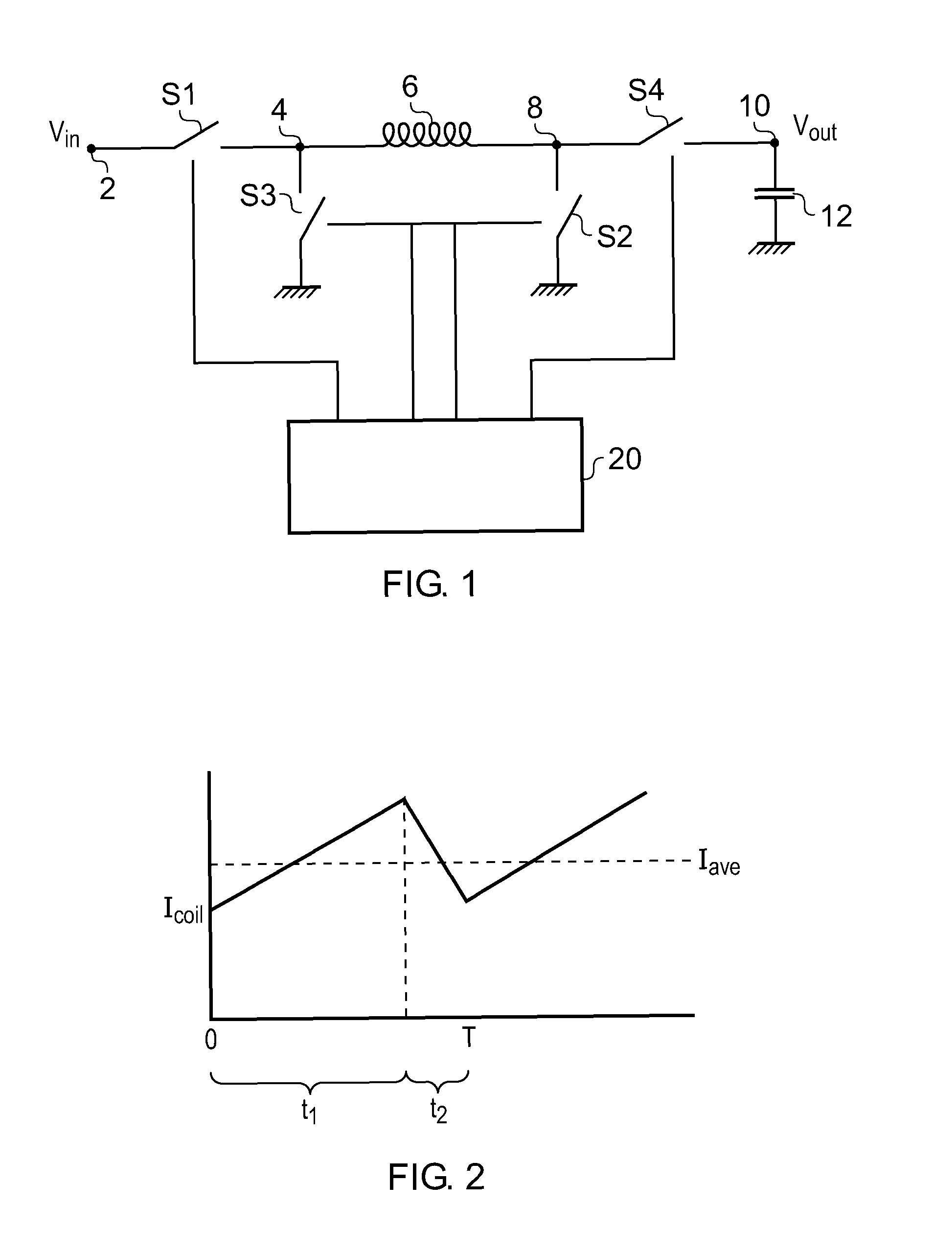
[0031]A DC to DC voltage converter operable to increase, i.e. BOOST, an input voltage Vin or to reduce, i.e. BUCK, an input voltage Vin is shown in FIG. 1.
[0032]The converter comprises an input node 2 which is connected to a first terminal 4 of an inductor 6 via a first electrically controlled switch S1. A second switch S2 extends between a second terminal 8 of the inductor 6 and ground. A third electrically controlled switch S3 extends between the first terminal 4 of the inductor 6 and a local ground. A fourth switch S4 extends between the second terminal 8 of the inductor 6 and an output node 10. A filtering capacitor 12 is connected between the output node 10 and ground. The switches S3 and S4 provide commutation paths and act as active rectifiers. They can be replaced by diodes if desired, and it is advantageous to have diodes placed in parallel with S3 and S4. In practice the may be several “local grounds”, which may be used to separate noisy parts of the circuit (and component...
PUM
 Abstract
Description
Claims
Application Information