Mat for acoustic apparatus

a technology for acoustic equipment and mats, applied in the field of mats, can solve the problems of cumbersome use, aluminum insulator is so heavy and bulky that it is difficult to form easily at low cost, vibration insulator fails to offer an adequate effect of absorption/reduction, etc., and achieves the effects of easy formation, low cost and light weigh

Inactive Publication Date: 2010-08-10
UEJIMA KAZUO
View PDF52 Cites 13 Cited by
  • Summary
  • Abstract
  • Description
  • Claims
  • Application Information

AI Technical Summary

Benefits of technology

[0026]According to the first aspect of the invention, the acoustic equipment mat is light in weight and is easily formed at low costs by arranging the inexpensive grain pieces of silica gel in a single layer. The formation of the mat does not require a costly precision processing such as metal working. Furthermore, the silica gel is harder than aluminum so that the mat having quite a small thickness substantially equal to a grain size of the silica-gel grain pieces may be disposed under a heavy acoustic equipment such as a speaker. The mat does not take up much space and is not cumbersome in use.
[0027]When the acoustic equipment mat having a single-layer structure of the grain pieces is disposed under the acoustic equipment such as an amplifier, speaker or the like, the individual grain pieces have their upper ends in point contact with the bottom of the acoustic equipment or the like and have their lower ends in point contact with the underlying floor or the like, so that the mat has quite a small area of contact with the acoustic equipment or the like. When the vibrations occurring at the casing and the like of the acoustic equipment are propagated to the mat, the quantity of vibrations reflected by a vibration incidence side (the upper ends of the grain pieces) and by a vibration exit side opposite therefrom (the lower ends of the grain pieces) is small. Hence, the mat notably reduces sound-quality degradation caused by the reflected vibrations or the like, as compared with the case where the aluminum insulator or the like is used.
[0028]Furthermore, this mat has not only a small thickness but also a great surface area because the mat is an assembly of plural grain pieces arranged in a layer. In addition, silicon dioxide as the major component of silica gel propagates the vibrations, such as sound waves, nearly as fast as aluminum. Therefore, the vibrations directly propagated from the acoustic equipment to the mat and the vibrations indirectly propagated to the mat as reflected from the lower-end side thereof are quite quickly dissipated in the atmosphere via the surfaces of the grain pieces.
[0029]Accordingly, the mat may be easily formed at low costs by using the silica-gel grain pieces, which negate the need for the costly precision processing such as metal working. Thus is provided a novel mat for use with acoustic equipment which is implemented in the light-weight, thin and compact configuration, which is capable of reducing the vibrations from the acoustic equipment such as an amplifier or speaker by dissipating the vibrations much more quickly and adequately as compared with the case where the aluminum insulator or the like is used, and which offers a great effect to improve the acoustic characteristic of the acoustic equipment as contributing to finely and richly expressive reproduction of the music sound or the like represented by the high-speed signals having the broad dynamic range.
[0030]According to the second aspect of the invention, the single layer structure of the grain pieces may be formed by mutually bonding the silica-gel grain pieces at their peripheries.
[0031]According to the third aspect of the invention, the flexible mesh substrate in a mesh-sheet form and the flexible thin-film adhesive substrate are bonded to each other as sandwiching the silica-gel grain pieces therebetween. In this case, the single-layer structure of the grain pieces may be formed in a manner that the respective meshes of the mesh substrate regularly locate the respective grain pieces for preventing the grain pieces from making mutual contact, that the grain pieces are uniformized in size to some extent so as to prevent the reproduced sounds from making unclear harmony, that the degradation of the grain pieces due to mutual contact is minimized, and that the reproduced sounds are prevented from making unclear harmony due to the size variations of the grain pieces. What is more, the laminate of these substrates is thin and flexible, thus constituting a thin, flexible mat.

Problems solved by technology

Hence, the vibration insulator fails to offer an adequate effect to absorb / reduce the vibrations occurring in the acoustic equipment such as the amplifiers and speakers during the sound reproduction or recording.
Naturally, the aluminum insulator cannot be easily formed at low costs.
In addition, the aluminum insulator is so heavy and bulky as to be cumbersome in use.

Method used


Image

  • Mat for acoustic apparatus
  • Mat for acoustic apparatus
  • Mat for acoustic apparatus

Examples


first embodiment

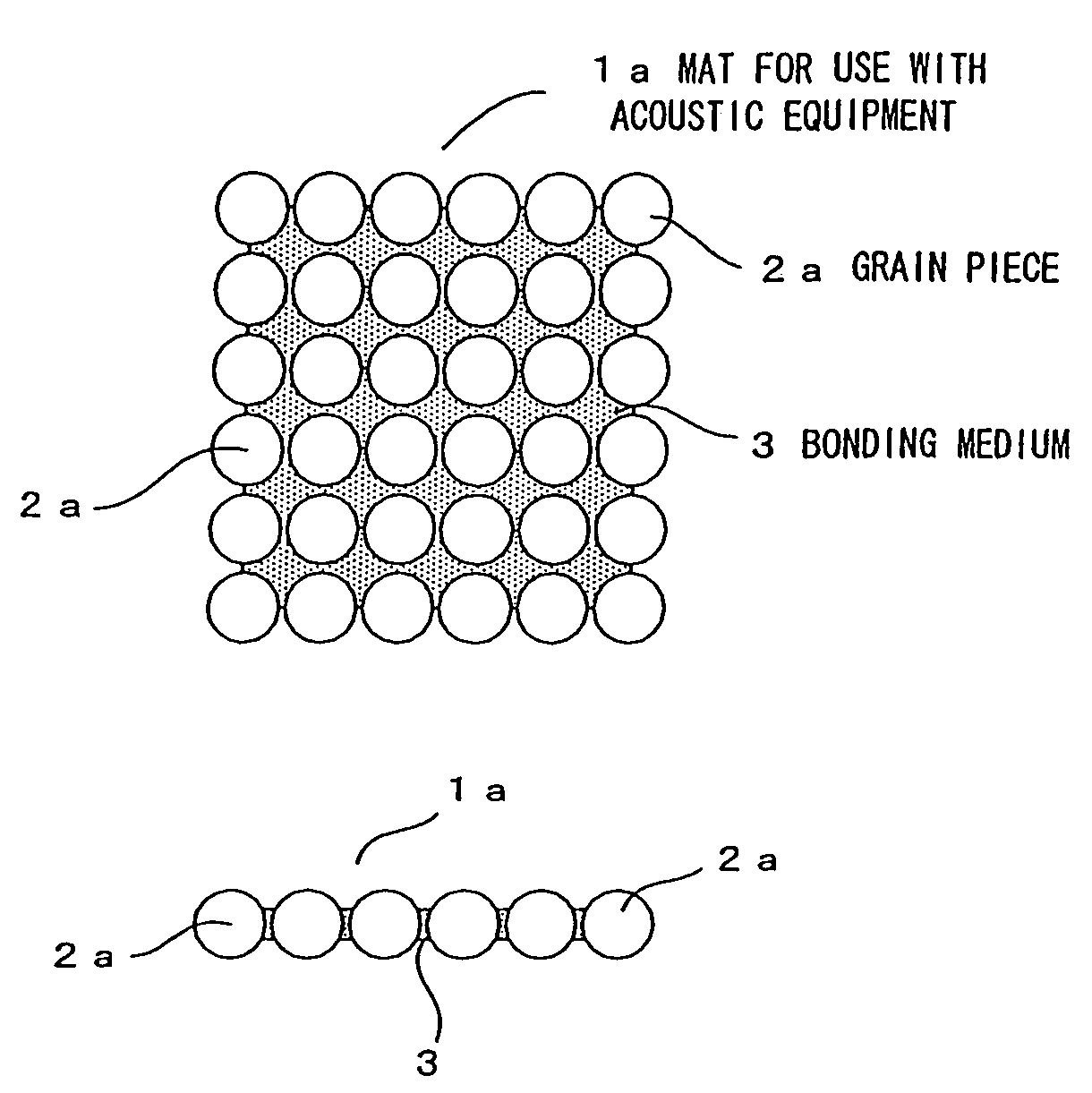
[0104]First, a first embodiment having a single-layer structure of silica-gel grain pieces (equivalent to the first and second aspects hereof) is described with reference to FIG. 1 to FIG. 6.

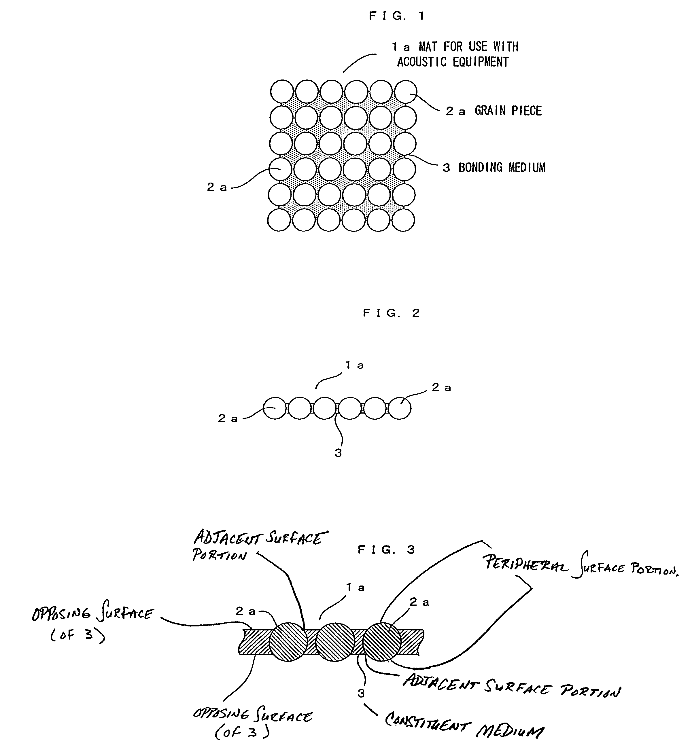
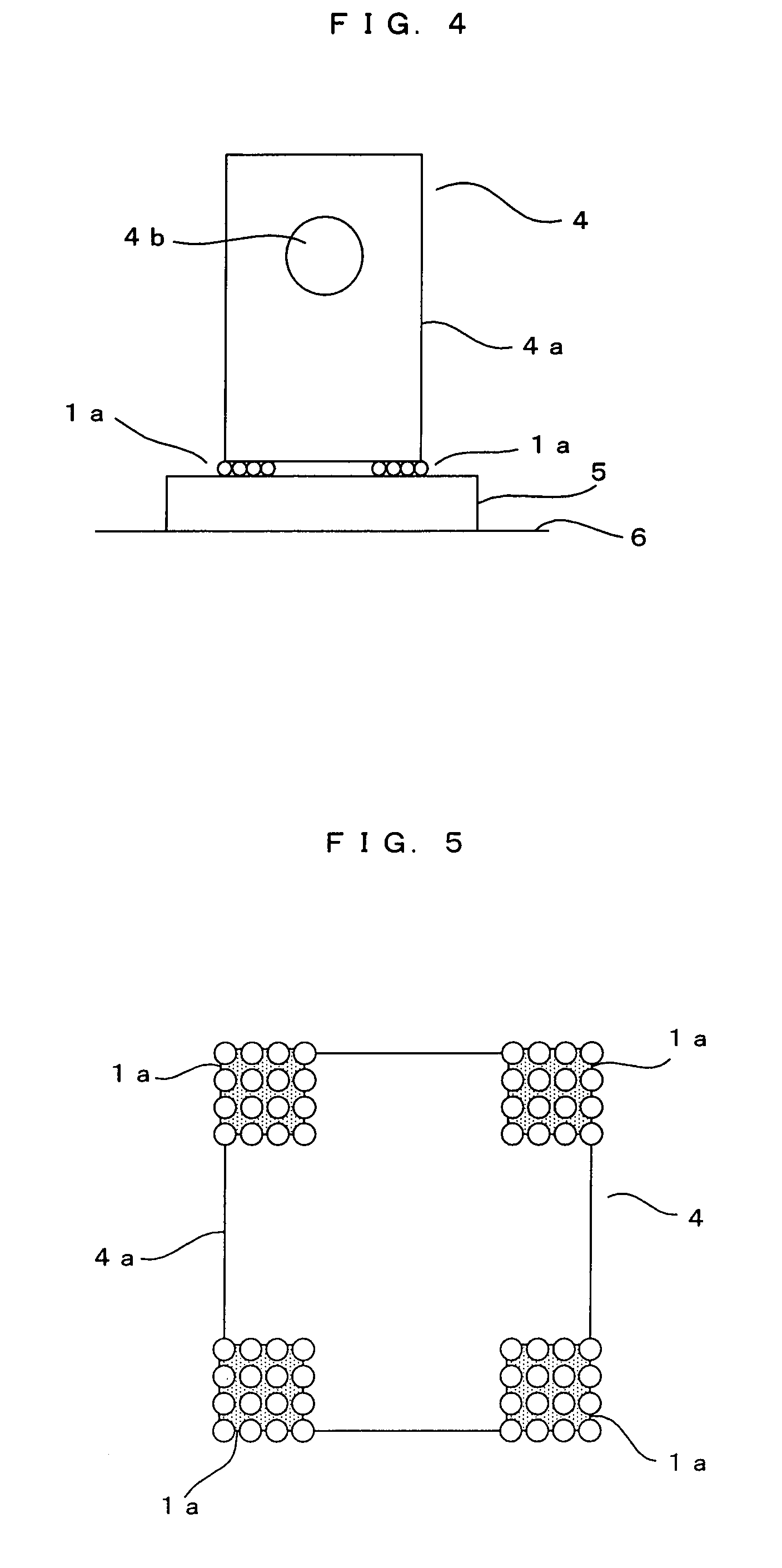
[0105]FIG. 1 is a plan view, FIG. 2 is a front view, and FIG. 3 is a fragmentary sectional view. FIG. 4 is a front view showing an example of use. FIG. 5 is a bottom plan view as seen from a bottom of a speaker shown in FIG. 4, a part of which is removed. FIG. 6 is a diagram explaining vibration dissipation. As shown in FIG. 1 and FIG. 2, an acoustic equipment mat 1a according to the embodiment is formed in a single-layer structure wherein a plurality of silica-gel grain pieces 2a are arranged in a single layer.

[0106]The grain pieces 2a may be silica-gel grain pieces having various diameters. From a practical standpoint, the grain pieces may preferably be substantially spherical grain pieces (spherical silica-gel grains) having diameters in the range of 1 mm to 10 mm and easily formed from a sil...

second embodiment

[0129]Next, a second embodiment illustrating another example of the above single-layer structure (equivalent to the third and fourth aspects hereof) is described with reference to FIG. 7 to FIG. 9.

[0130]FIG. 7 is a plan view showing an acoustic equipment mat 1aa, FIG. 8 is a back-side view thereof, and FIG. 9 is a front view thereof. As shown in these figures, the acoustic equipment mat 1aa is formed by bonding together a flexible mesh substrate 18 in a mesh-sheet form and a more flexible thin-film adhesive substrate 19 as interposing the grain pieces 2a between these substrates.

[0131]According to the embodiment, the mesh substrate 18 is prepared by cutting a glass-fiber mesh tape to a suitable length, the mesh tape commercially available as a mesh tape for repairing gaps or cracks in a building material. If the grain pieces 2a have grain sizes on the order of 2 mm, each mesh 18a of the mesh substrate has a size of about 2 mm×2 mm, and each vertical or horizontal strand between adjo...

third embodiment

[0145]Next, a third embodiment illustrating still another example of the above single-layer structure (equivalent to the fifth and sixth aspects hereof) is described with reference to FIG. 10 to FIG. 13.

[0146]FIG. 10 is a plan view showing an acoustic equipment mat 1ab, FIG. 11 is a back-side view thereof, and FIG. 12 is a sectional front view thereof. FIG. 13 is a diagram explaining how a grain piece is locked in the mat. As shown in the figures, the acoustic equipment mat 1ab includes a case member 20 formed of a flexible pile weave fabric.

[0147]The case member 20 according to the embodiment includes: an accommodating portion 20a formed by cutting pile weave towel cloth to a 5 cm×5 cm size for example, the towel cloth commercially available as body towel, bath towel and such; and a paper tape 20b or an adhesive paper-based tape for sandwichingly covering edges of the four sides of the accommodating portion 20a in order to prevent the edges from fraying.

[0148]The above pile weave t...


PUM


Abstract

An acoustic equipment mat is formed by arranging plural grain pieces of inexpensive silica gel in a single layer. When the mat is disposed under an acoustic equipment, the grain pieces have their upper ends in point contact with a bottom or the like of the acoustic equipment and have their lower ends in point contact with the underlying floor or the like. Hence, the mat 1a is notably reduced in the area of contact with the acoustic equipment or the like, so as to reduce the reflection of vibrations. In addition, the mat 1a is capable of extremely quickly dissipating, in the atmosphere, the vibrations directly propagated to the upper-end side thereof and the vibrations indirectly propagated thereto as reflected by the lower-end side thereof.

Description

TECHNICAL FIELD[0001]The present invention relates to a mat for use with acoustic equipment, which is disposed under an acoustic equipment such as a speaker or amplifier so as to improve the acoustic characteristics of the equipment.BACKGROUND ART[0002]In the field of a so-called audio system, the recent advent of digital acoustic equipment such as CD players and MD players has made it possible to appreciate music and the like recorded on CDs and MDs by reproducing high-speed signals having a broad dynamic range.[0003]In this case, the influence of vibrations of casings, circuit components and the like of the acoustic equipment, such as amplifiers and speakers, of the audio system is an important matter if these pieces of music are to be reproduced with the finest and richest possible musical expression.[0004]This problem is encountered not only in music appreciation using a full-scale audio system but also in music appreciation using a compact stereo system or a radio-cassette play...

Claims


Application Information

Patent Timeline
Patent Type & Authority Patents(United States)
IPC IPC(8): E04B1/84
CPCF16F1/3737F16F9/30G11B33/00H04R23/00G10K11/16G10K11/162H04R1/02G10K11/00
Inventor UEJIMA, KAZUO
Owner UEJIMA KAZUO
Why Eureka
Try Eureka