Energy recovering method and system in hydraulic lift device of battery operated industrial trucks
a technology of energy recovery and hydraulic lift, which is applied in the direction of elevators, fluid couplings, sustainable manufacturing/processing, etc., to achieve the effect of reducing the responsivity of speed change, saving installation space, and reducing the total weight of the system
- Summary
- Abstract
- Description
- Claims
- Application Information
AI Technical Summary
Benefits of technology
Problems solved by technology
Method used
Image
Examples
first embodiment
The First Embodiment
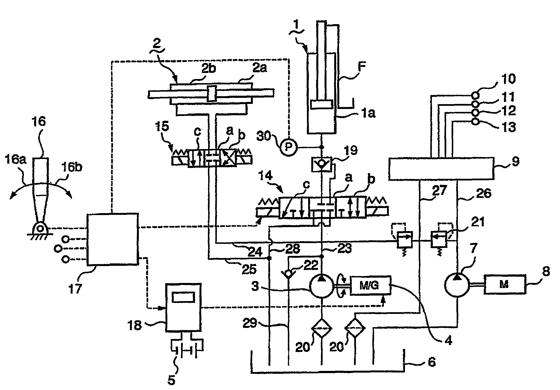
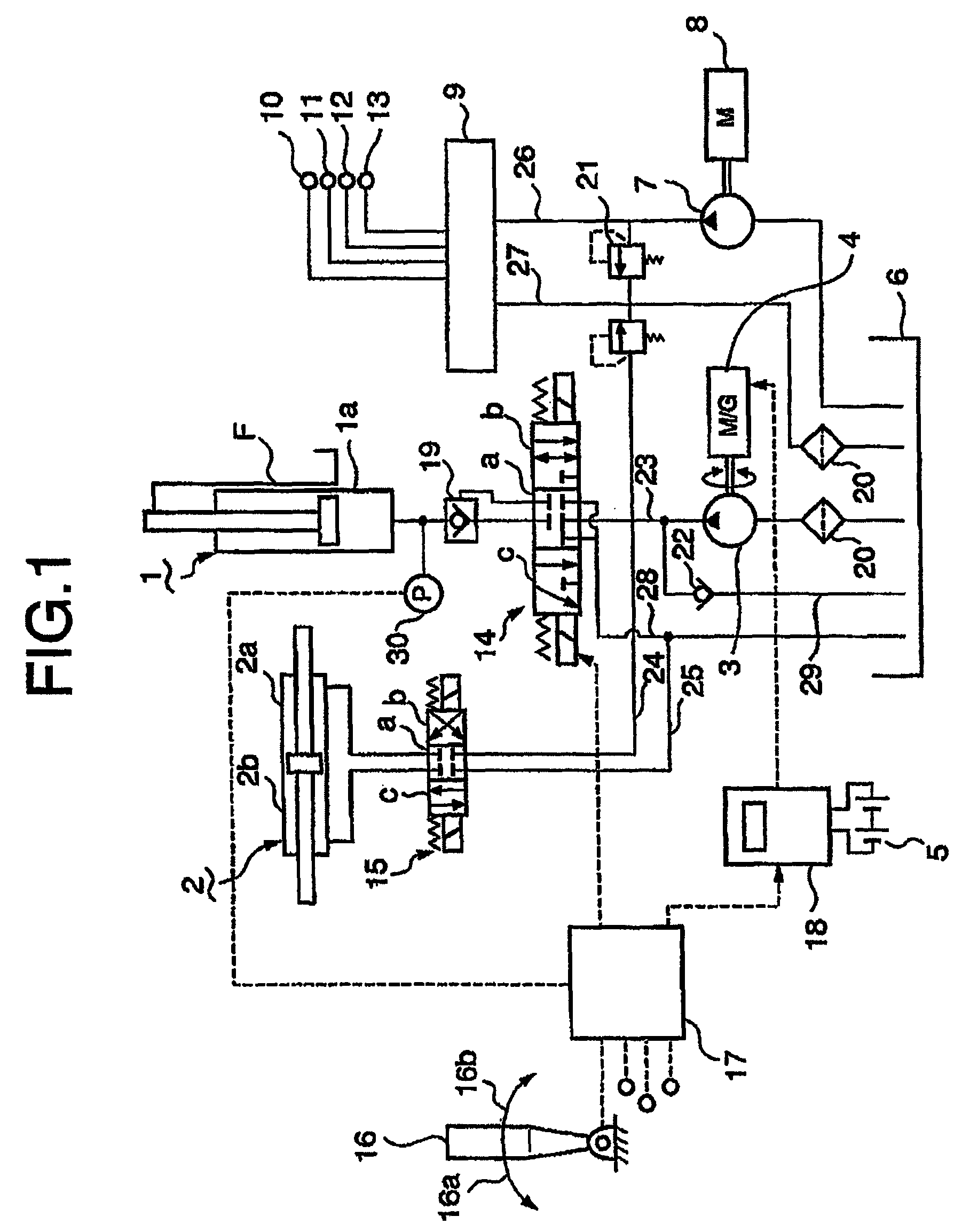
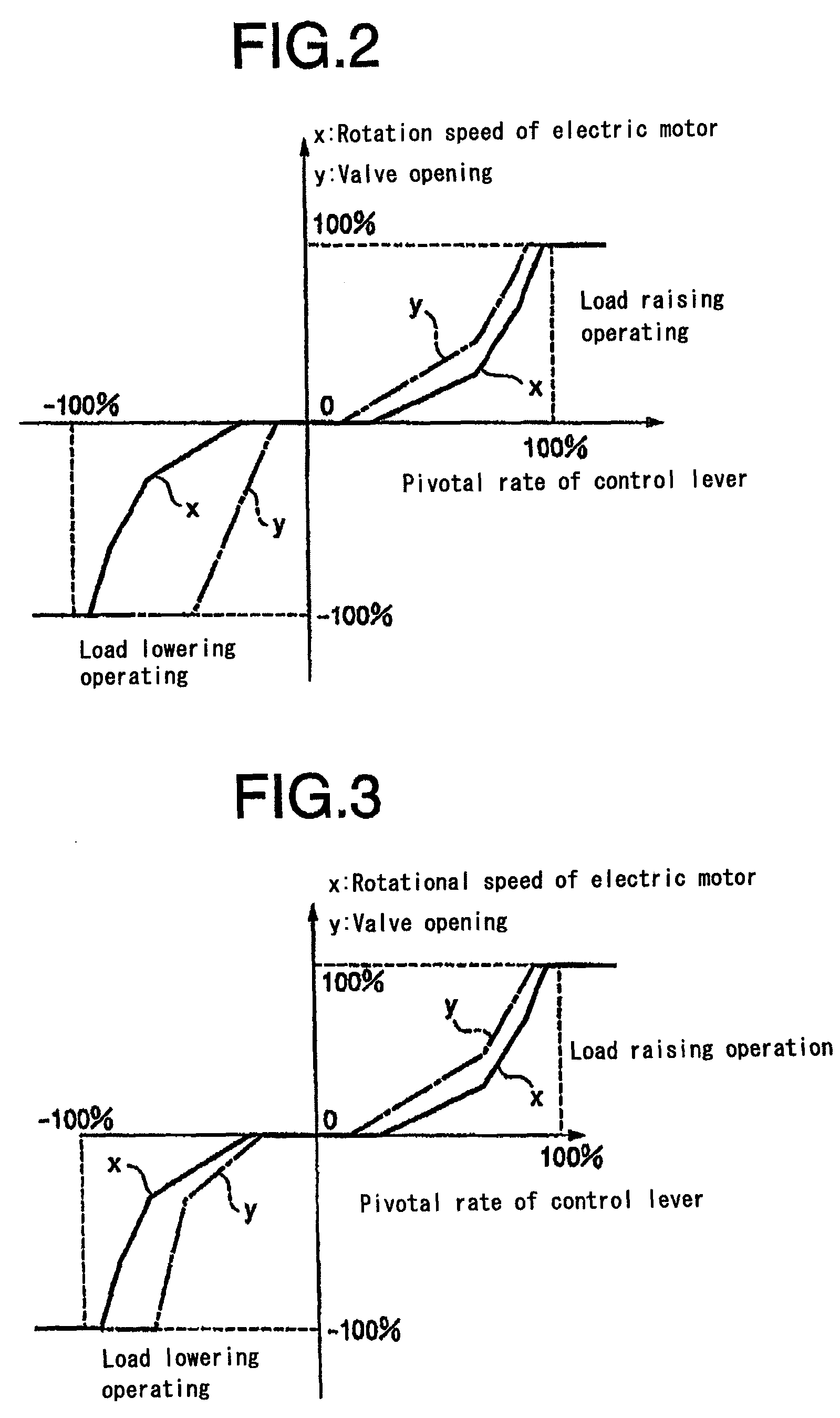
[0053]FIG. 1 is a schematic hydraulic lift circuit of the first embodiment according to the invention, and FIG. 2 is a diagram showing rotation speed x of the electric motor and the amount of opening of the control valve 14 vs. the pivotal rate y of the control lever in the first embodiment.
[0054]In FIG. 1, reference numeral 1 is a lift cylinder for lifting a fork F (lift means) of a forklift truck, 1a is a bottom oil chamber of the lift cylinder 1, 2 is a hydraulic cylinder composing a second actuator for driving another attachment of the forklift truck, for example, a driving device for driving claws not shown of the fork F. Reference numeral 3 is a hydraulic pump for supplying working oil from an oil tank 6 to oil chambers of the lift cylinder 1 and hydraulic cylinder 2, 5 is a set of batteries for supplying electricity to the electric motor 4.
[0055]Reference numeral 7 is a second hydraulic pump, which is driven by an electric motor 8, sucks the working oil in...
second embodiment
The Second Embodiment
[0063]FIG. 3 shows another example (the second embodiment) of controlling the lowering speed through the control of rotation speed of the electric motor 4 and the opening of the control valve 14 in the lowering operation. In the embodiment, as shown in FIG. 3, the lowering speed is controlled by controlling the opening of the control valve 14 in the initial range where the lowering speed is small and gentle control of the lowering speed is needed, and the lowering speed is controlled through the control of rotation speed of the electric motor 4 with the opening of the control valve 14 being steeply increased in the range where the lowering speed is large as is at the rated speed lowering. In this way, energy recovery efficiency can be increased by performing delicate control of the lowering speed.
third embodiment
The Third Embodiment
[0064]FIG. 4 shows a further example (the third embodiment) of controlling the raising and lowering speed of the fork F. In the system of the first embodiment shown in FIG. 1, oil pressure P in the bottom oil chamber 1a of the lift cylinder 1, which pressure being dependent on the weight of the load, is detected by the pressure sensor 30, and the opening of the control valve 14 and the rotation speed of the electric motor 4 with respect to the pivotal rate of the control lever 16 are controlled according to the detected pressure P.
[0065]By controlling with the weight of the load on the fork F taken into consideration like this, the lowering of the fork F when the load on the fork F is heavy is performed smoothly, and energy recovery efficiency can be increased.
PUM
 Abstract
Description
Claims
Application Information
 - R&D
- Intellectual Property
- Life Sciences
- Materials
- Tech Scout
- Unparalleled Data Quality
- Higher Quality Content
- 60% Fewer Hallucinations
Browse by: Latest US Patents, China's latest patents, Technical Efficacy Thesaurus, Application Domain, Technology Topic, Popular Technical Reports.
© 2025 PatSnap. All rights reserved.Legal|Privacy policy|Modern Slavery Act Transparency Statement|Sitemap|About US| Contact US: help@patsnap.com


