Storage hopper, and combination weighing device and packaging device provided with the same

a technology of combination weighing device and packaging device, which is applied in the direction of instruments, packaging goods types, de-stacking articles, etc., can solve the problems of high device height, inability to easily flow in from above, and the need for replacement of the insertion cylinder, etc., to achieve the effect of reducing the device heigh

Inactive Publication Date: 2010-08-10
ISHIDA CO LTD
View PDF20 Cites 3 Cited by
  • Summary
  • Abstract
  • Description
  • Claims
  • Application Information

AI Technical Summary

Benefits of technology

[0012]It is therefore an object of the present invention to provide a storage hopper capable of reducing the tailing of articles discharged from the storage hopper regardless of the state of the articles, and capable of achieving a further acceleration of the process, and a combination weighing device and a packaging device provided with the same.
[0029]In addition, when the storage hopper according to the present invention is configured as part of a combination weighing device or part of a packaging device, it is possible to reduce the height of the device by placing the article holding state changing unit within the height of the storage portion.

Problems solved by technology

However, the device described in Japanese Utility Model Laid-Open Publication No. 62-143601 has a problem that the height of the device becomes high since the storage hopper and the second storage hopper are disposed above and below.
The device also has a problem that the insertion cylinder needs to be replaced each time the type of articles to be processed is changed.
In addition, when the diameter of the insertion cylinder is small, there is a problem that articles cannot easily flow in from above.
Further, when the high speed operation is attempted, the use of the conventional storage hopper causes the tailing of articles due to the contact resistance between the articles and the inner surface of the storage hopper (or the insertion cylinder).
Although this problem cannot be overlooked, none of the conventional devices described above mentions anything about this problem.

Method used


Image

  • Storage hopper, and combination weighing device and packaging device provided with the same
  • Storage hopper, and combination weighing device and packaging device provided with the same
  • Storage hopper, and combination weighing device and packaging device provided with the same

Examples


first embodiment

Configuration of Combination Weighing Device

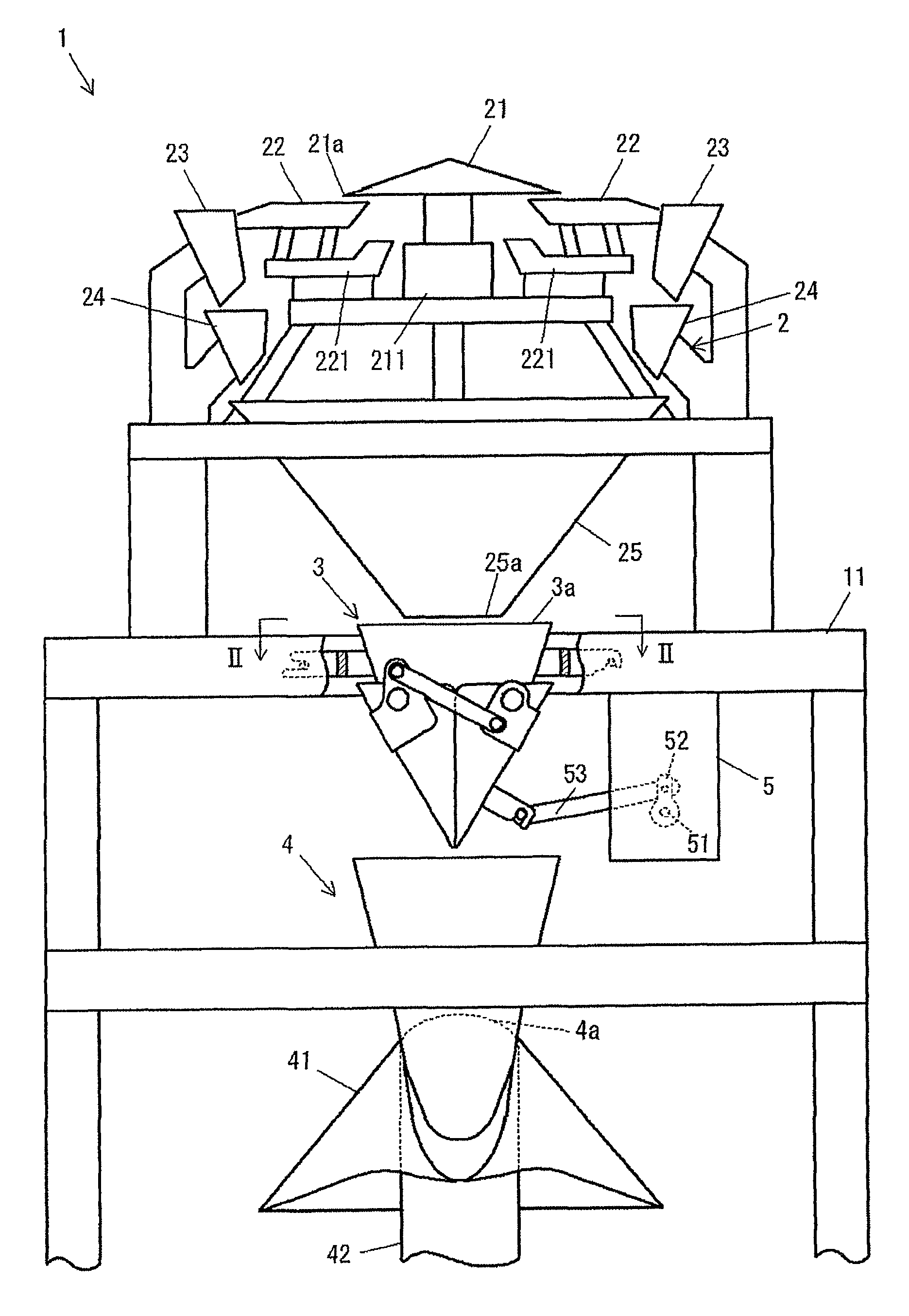
[0049]As shown in FIG. 1, a combination weighing device 1 according to the present embodiment is disposed in the space above a packaging device 4 and includes a machine table 11, a weighing unit 2, a storage hopper 3, and the like. The weighing unit 2 is supported by the machine table 11 and discharges articles weighed to a predetermined weight at each predetermined time interval. The storage hopper 3 receives from a top opening 3a the articles weighed to a predetermined weight by the weighing unit 2, temporarily stores the articles, and supplies the articles to a receiving opening 4a of the packaging device 4 disposed below.

[0050]The weighing unit 2 includes a dispersion table 21, a plurality of vibrating troughs 22 . . . 22, a plurality of pool hoppers 23, a plurality of weighing hoppers 24 . . . 24, and a collection chute 25.

[0051]The articles are dropped to the dispersion table 21 from an article supply device (not shown) disposed abov...

second embodiment

Configuration of Combination Weighing Device

[0078]In a second embodiment, as shown in FIGS. 10 to 12, gates 131, 132 of a storage hopper 103 includes base portions 131a, 132a and lateral side portions 131b, 131c, 132b, 132c. The lateral side portions 131b, 131c, 132b, 132c extend in the direction perpendicular from both lateral ends of the base portions 131a, 132a. An opening portion surrounded by the lateral side portions 131b, 131c, 132b, 132c is formed at the top end of the gates 131, 132. As shown in FIG. 10, this opening portion has a quadrangular shape in a plan view.

[0079]In addition, as well illustrated in FIG. 11, a holding member 164 has a generally inverted isosceles triangular shape in a front view, and includes a base surface portion 164a and lateral side portions 164b, 164b. The lateral side portions 164b, 164b extend from both lateral upper portion of the base surface portion 164a toward the opposite holding member 164 side and then to the left and right. When the gat...


PUM

PropertyMeasurementUnit
sizeaaaaaaaaaa
volumeaaaaaaaaaa
timeaaaaaaaaaa

Abstract

A storage hopper temporarily stores articles supplied from above and then discharges the articles downward. The storage hopper includes a holding member of an article holding change mechanism in a storage portion. The holding member changes a state in which the articles are held in the storage portion according to a state of the articles.

Description

[0001]This U.S. national phase application claims priority to Japanese Patent Application No. 2006-156993 filed on Jun. 6, 2006. The entire disclosure of Japanese Patent Application No. 2006-156993 is hereby incorporated herein by reference.TECHNICAL FIELD[0002]The present invention relates to a storage hopper that temporarily stores articles supplied from above and then discharges the articles downward, and a combination weighing device and a packaging device provided with the same.BACKGROUND ART[0003]As is well known, among combination weighing devices, there is a type of device in which articles discharged from a plurality of weighing hoppers selected by combination calculation are delivered to storage hoppers via a chute or the like, temporarily stored in these storage hoppers, and then discharged to a downwardly disposed packaging device and the like.[0004]When this type of combination weighing device and packaging device are used, the opening and closing operation of the weigh...

Claims


Application Information

Patent Timeline
Patent Type & Authority Patents(United States)
IPC IPC(8): B65G47/04
CPCB65B3/26B65B37/16B65D88/28B65D90/623G01G19/393B65D2590/662
Inventor NAKAGAWA, YUKIOHATTORI, HIROSHIHAYAKAWA, TERUO
Owner ISHIDA CO LTD
Why Eureka
Try Eureka