Battery float management

a technology of battery float and float current, which is applied in the direction of cell components, sustainable manufacturing/processing, instruments, etc., can solve the problems of excessive corrosion of the positive grid, inability to supply the required terminal voltage the current at the required voltage, and large amounts of energy storag

Active Publication Date: 2010-08-10
EATON INTELLIGENT POWER LTD
View PDF11 Cites 2 Cited by
  • Summary
  • Abstract
  • Description
  • Claims
  • Application Information

AI Technical Summary

Problems solved by technology

Depending on the load size and required backup time, large amounts of energy storage are often necessary.
The traditional failure mechanism of lead acid batteries is excessive corrosion of the positive grid.
Eventually this resistance rises to a point where the cell can no longer supply the necessary current at the required terminal voltage.
A further complication is that 2 Volt cells are connected in series to produce the desired system voltages (typically 24 or 48 Volts).
However it is becoming increasingly apparent with many “long life” VRLA batteries that either poor design, or poor quality manufacturing, results in the cells failing prematurely in the field.
This is believed to be due to internal electrode balance problems, and in particular negative plate discharge.
While this rate of negative electrode discharge is extremely low, the cumulative effects of months or years of float charge can be significant.
Furthermore, as the applied polarisation is supported entirely by the positive electrode, increased rates of grid corrosion, gassing, and possible dryout must result.
As VRLA cells basically function as a sealed unit, it is difficult to insert the reference electrode without disturbing the seal and modifying the cells' characteristics.

Method used


Image

  • Battery float management
  • Battery float management
  • Battery float management

Examples


Embodiment Construction

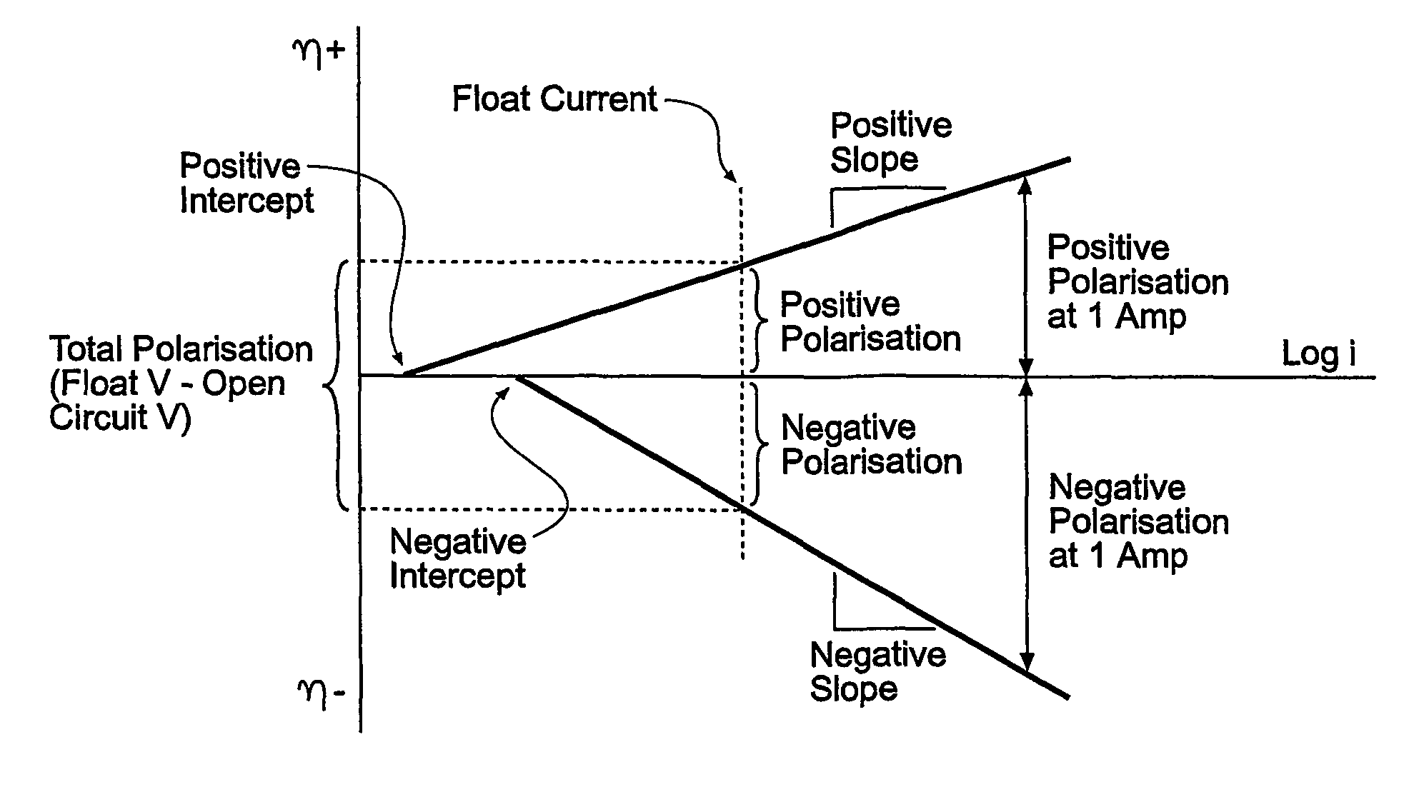
[0060]The invention allows battery float management to be implemented through modelling and sensing the battery positive and negative electrode contributions. Further information relating to the invention and its implementation can be found in the PhD thesis of Phillip M Hunter entitled “VLRA Battery Float Charge: Analysis and Operation” which is incorporated herein by reference. The invention has the advantage that additional hardware is not required. Electrode polarisation can be sent directly from the battery external terminals by the use of software. Knowing the status of electrode polarisation allows the state of charge of their treat identified. Therefore the required action can be implemented to recover balanced charge polarisation before any permanent damage to the battery takes place. The invention may also be used to identify any damage to the battery that has taken place through successive charge or test procedures.

[0061]Through modelling the steady state and transient ch...


PUM

PropertyMeasurementUnit
voltageaaaaaaaaaa
voltageaaaaaaaaaa
float voltageaaaaaaaaaa

Abstract

The invention relates to a new VRLA battery float model. The model covers the steady state and transient float charge behavior of both positive and negative electrodes. Backup analysis verifies the internal polarization distribution for a conventional 2V-cell polarization behaviors can be identified without the need for a physical reference electrode. The estimated individual electrode polarization allows early detection of common failure modes like negative plate discharge as well as a reference for float voltage optimisation. Furthermore, the positive polarization relating to minimum grid corrosion may be correlated with the occurrence of the peak of a “Tafel” like resistance used by the model. The model encourages utilisation of low signal perturbation for testing a cell's state of health and state of charge conditions while at float.

Description

RELATED APPLICATIONS[0001]The present application is a 35 U.S.C. §371 national phase application of PCT International Application No. PCT / NZ2004 / 000141, having an international filing date of Jul. 2, 2004 and claiming priority to U.S. Provisional Application No. 60 / 484,571, filed Jul. 2, 2003, the disclosures of which are incorporated herein by reference in their entireties. The above PCT International Application was published in the English language and has International Publication No. WO 2005 / 013409.FIELD OF THE INVENTION[0002]This invention relates to float to charge behaviour of batteries, and has particular application to valve regulated lead acid (VRLA) batteries.BACKGROUND[0003]A continuous power supply is critical to the success of many applications. Telecommunications systems are a prime example of this, as they are expected to function continuously in the event of a power outage. A typical telecommunication power system converts the AC grid power to 48 volts DC, and then...

Claims


Application Information

Patent Timeline
Patent Type & Authority Patents(United States)
IPC IPC(8): G01N27/416H01M2/12H01M10/34H01M10/44H01M10/48
CPCG01R31/362G01R31/3651H01M10/121H01M10/42H01M10/4285H01M10/44H01M10/48Y02E60/126G01R31/367G01R31/3835Y02E60/10Y02P70/50
Inventor AL-ANBUKY, ADNANHUNTER, PHILLIP
Owner EATON INTELLIGENT POWER LTD
Why Eureka
Try Eureka