Apparatus and method for spatial encoding of a search space

a technology of spatial encoding and apparatus, applied in surveying and navigation, distance measurement, instruments, etc., can solve the problems of refractive turbulence effect, difficult detection of shsos, and increased difficulty in operation

Inactive Publication Date: 2010-08-10
THE UNITED STATES OF AMERICA AS REPRESENTED BY THE SECRETARY OF THE NAVY
View PDF11 Cites 47 Cited by
  • Summary
  • Abstract
  • Description
  • Claims
  • Application Information

AI Technical Summary

Benefits of technology

[0011]An apparatus provides spatial encoding of a search space by use of a radiation source providing a plurality of beams. At least one radiation source is used and is capable of providing a predetermined type of radiation in the form of a plurality of beams arrayed along at least one directional axis, with the beams arranged in successive alignment to exhibit a directional component character

Problems solved by technology

Distortions include refractive turbulence effects due to a non-uniform index of refraction distribution.
Since water is a type of acoustically obscuring medium, detection of SHSOs can be difficult.
This operation is made more difficult when the object is within an obscuring medium and/or the object is a moving object.
An added complication arises when the object is near a boundary or interface between two mediums.
A challenging problem involves detecting and tracking surface-hugging moving object (SHMO) within an obscuring medium (a medium such as water or air which is capable of scattering, absorbing, and/or distorting the propagation of acoustic or electromagnetic (EM) radiation, respectively).
Consider the problem of detecting and tracking SHFOs.
Active detection and tracking methods (such as radar) and passive detection and tracking methods, such as detecting infrared emissions or scattered EM radiation due to natural illumination, have been employed with limited success.
A tim

Method used


Image

  • Apparatus and method for spatial encoding of a search space
  • Apparatus and method for spatial encoding of a search space
  • Apparatus and method for spatial encoding of a search space

Examples


Embodiment Construction

Acronyms

[0020]1-D—One Dimensional[0021]2-D—Two Dimensional[0022]3-D—Three Dimensional[0023]AFV—Autonomous Flying Vehicle[0024]AM—Amplitude Modulated[0025]ASV—Autonomous Swimming Vehicle[0026]CT—Computed Tomography[0027]CW—Continuous Wave[0028]DIAL—Differential Absorption LIDAR[0029]EM—Electromagnetic Radiation[0030]FM—Frequency Modulated[0031]GPS—Global Positioning System[0032]ITF—Image Transfer Function[0033]LED—Light Emitting Diode[0034]LIDAR—Light Detection and Ranging[0035]PET—Positron Emission Tomography[0036]SERS—Spatially Encoded Radiation Signal[0037]SHFO—Surface-Hugging Flying Object[0038]SHMO—Surface-Hugging Moving Object[0039]SHSO—Surface-Hugging Swimming Object[0040]SPECT—Singe Photon Emission Computed Tomography[0041]TOF—Time of Flight[0042]UV—Ultra Violet

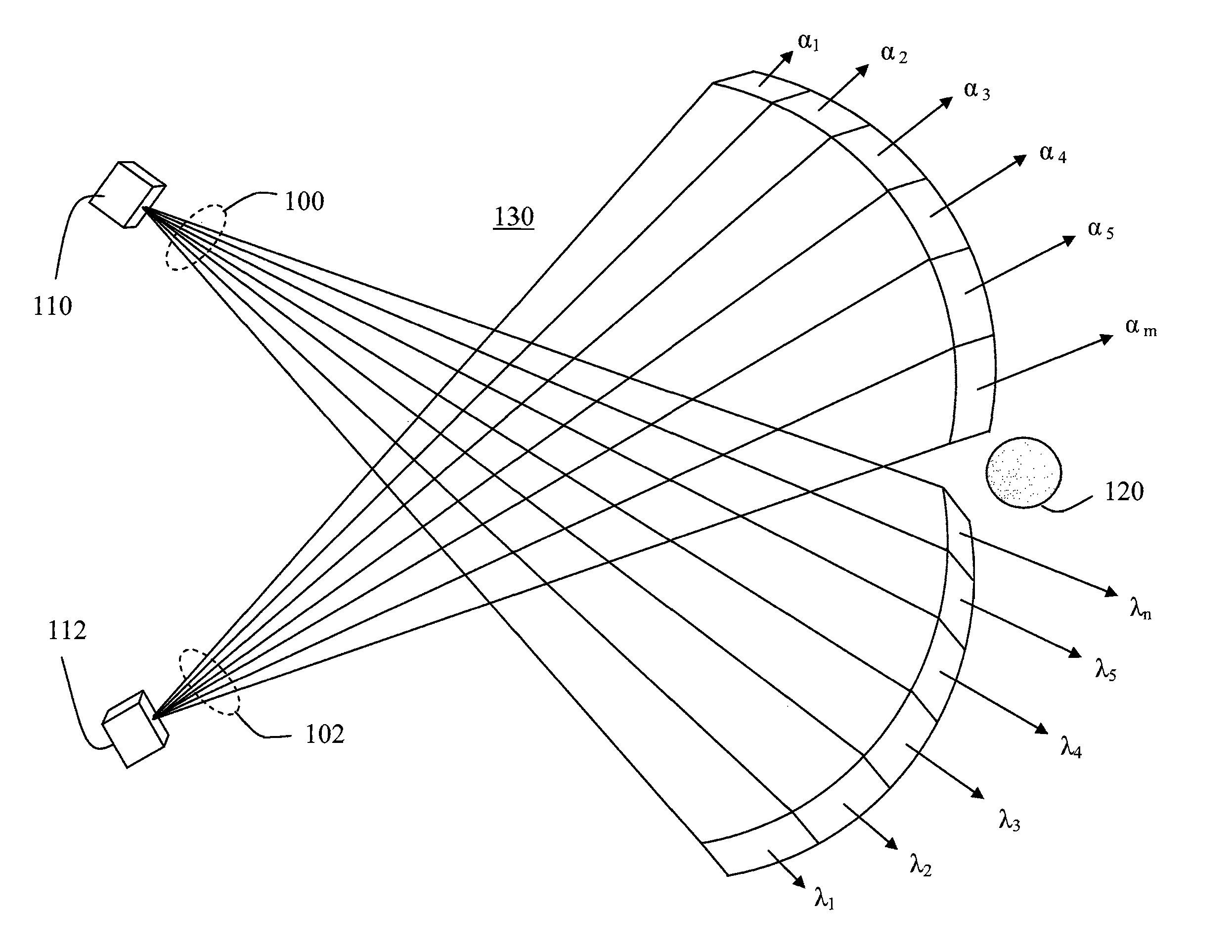
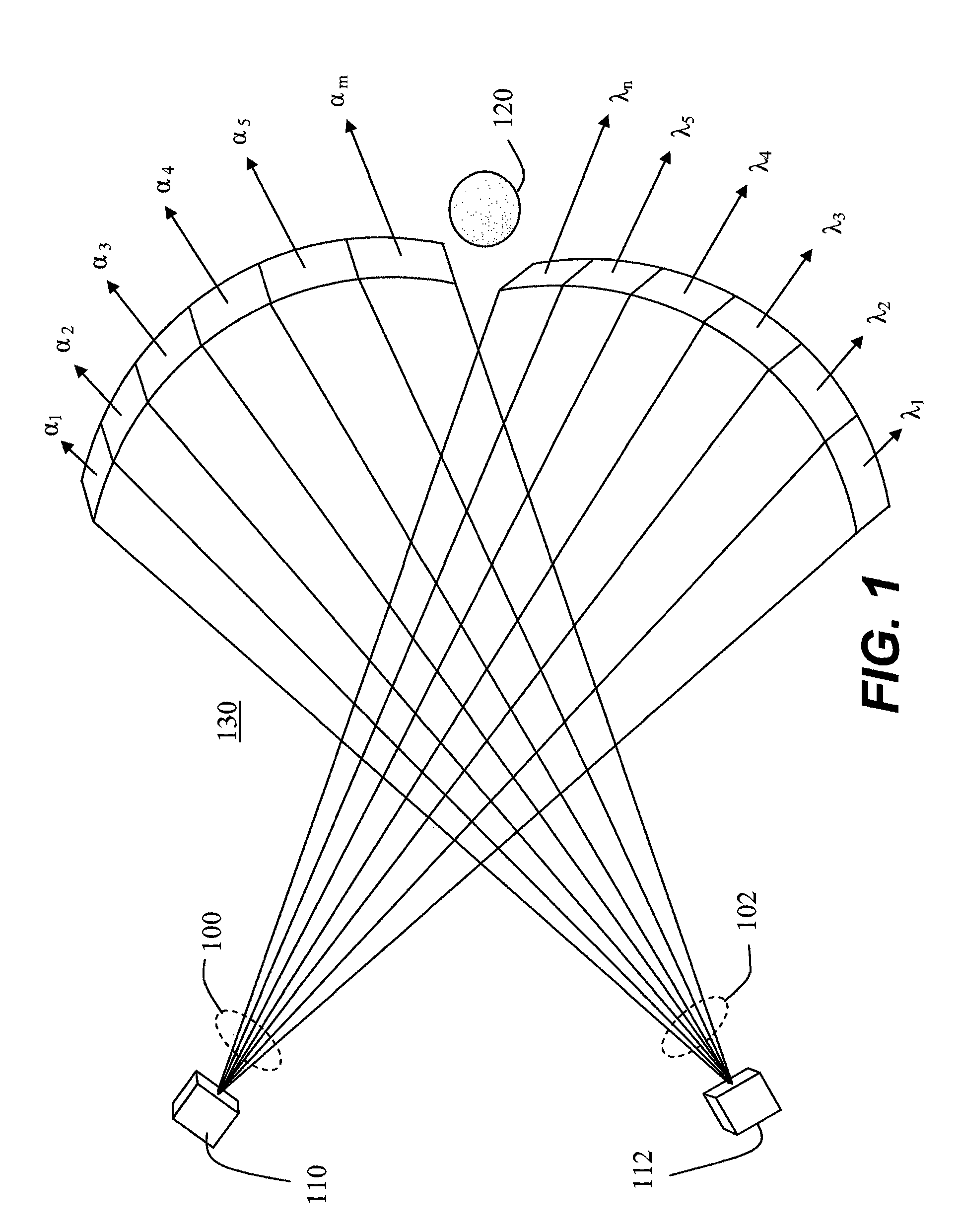
[0043]The present invention provides a method and apparatus for the detection and tracking of stationary and moving objects, in particular surface-hugging moving objects (SHMOs), within a search space. The search space...


PUM


Abstract

Spatial encoding of a search space is achieved by an array of radiation or acoustic energy detectors receiving data from at least one radiation or energy source. At least one radiation source capable of providing a predetermined type of radiation is used. The radiation may be in the form of a plurality of beams arrayed along at least one directional axis, and arranged in successive alignment to exhibit a directional component. The directional component is characterized by a frequency variance between successive beams in accordance with direction and disposed so radiation therefrom propagates within the search space. At least one radiation detector capable of detecting the radiation is provided, and is disposed to detect at least that type of radiation.

Description

CROSS-REFERENCE TO RELATED APPLICATION[0001]This application is a continuation-in-part of U.S. patent application Ser. No.: 11 / 499,969, filed 20 Jul. 2006, now U.S. Pat. No. 7,589,827 entitled “System and Method for Detecting an Object in a Search Space” (Navy Case # 83775), hereby incorporated by reference herein in its entirety for its teachings.FEDERALLY-SPONSORED RESEARCH AND DEVELOPMENT[0002]This invention (Navy Case No. 98291) was developed with funds from the United States Department of the Navy. Licensing inquiries may be directed to Office of Research and Technical Applications, Space and Naval Warfare Systems Center, San Diego, Code 2112, San Diego, Calif., 92152; telephone (619)553-2778; email: T2@spawar.navy.mil.FIELD OF THE INVENTION[0003]The present invention relates to the detection or detection and tracking of objects within a search space of a fixed or moving site. Such detection can be used to detect objects associated with a platform such as a vessel or a plane; a...

Claims


Application Information

Patent Timeline
IPC IPC(8): G01C3/08
CPCG01S13/48G01S13/52G01S13/74G01S15/46G01S17/46G01S13/862G01S7/4056G01S7/4972G01S15/89G01S2007/403G01S2007/4091G01S2007/4034G01S13/867G01S7/403G01S7/4034G01S7/4091
Inventor NELSON, ROBERT SIGURD
Owner THE UNITED STATES OF AMERICA AS REPRESENTED BY THE SECRETARY OF THE NAVY
Why Eureka
Try Eureka