Sound sources separation and monitoring using directional coherent electromagnetic waves

a technology of electromagnetic waves and sound sources, applied in electromagnetic transmission, magnetic measurements, transmission, etc., can solve the problems of poor sound source separation ability, time-consuming and not always cost-effective digital signal processing (dsp) techniques, and reduce the quality of sound sensing, so as to eliminate the noise component

Inactive Publication Date: 2010-08-17
VOCALZOOM SYST
View PDF9 Cites 21 Cited by
  • Summary
  • Abstract
  • Description
  • Claims
  • Application Information

AI Technical Summary

Benefits of technology

[0012]The present invention discloses an apparatus and a method that achieve physical separation of sound sources by pointing directly a beam of coherent electromagnetic waves (i.e. laser). Analyzing the physical properties of a beam reflected from the vibrations generating sound source enable the reconstruction of the sound signal generated by the sound source, eliminating the noise component added to the original sound signal. In addition, the use of multiple electromagnetic waves beams or a beam that rapidly skips from one sound source to another allows the physical separation of these sound sources. Aiming each beam to a different sound source ensures the independence of the sound signals sources and therefore provides full sources separation.

Problems solved by technology

The main drawback of currently available remote sound sensing systems is their poor ability of sound sources separation.
By relying on a beam reflected from a vibrating surface rather than directly the sound generating object, the systems according to the prior art are actually sensing the sound source's ambient, which may include noise that inherently reduces the quality of the sound sensing.
Noise filtering, as well as blind sources separation (the separation of the different unrelated sound sources) has to be performed using time-consuming and not always cost-effective digital signal processing (DSP) techniques.

Method used


Image

  • Sound sources separation and monitoring using directional coherent electromagnetic waves
  • Sound sources separation and monitoring using directional coherent electromagnetic waves
  • Sound sources separation and monitoring using directional coherent electromagnetic waves

Examples


Embodiment Construction

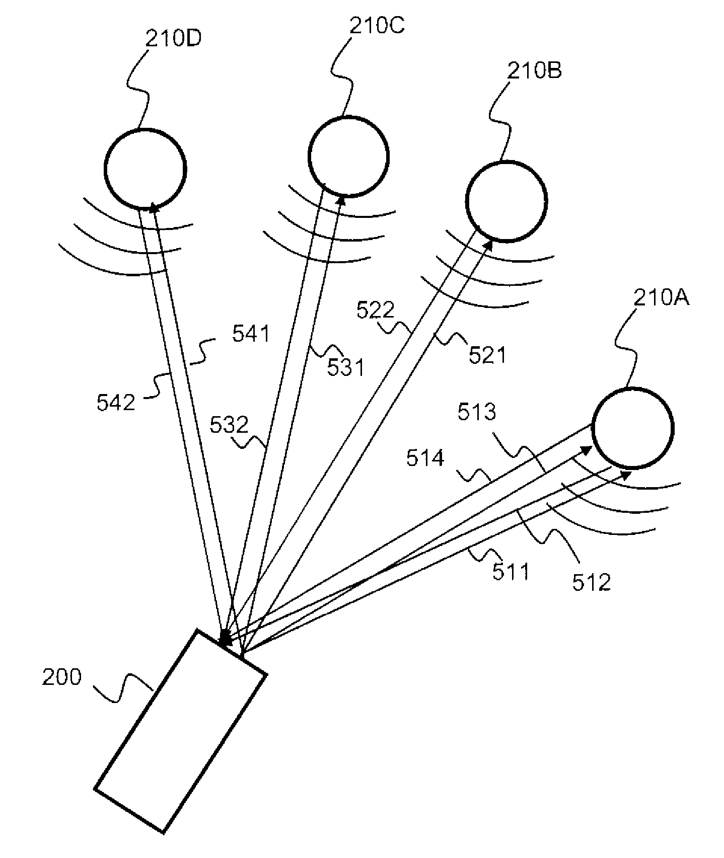
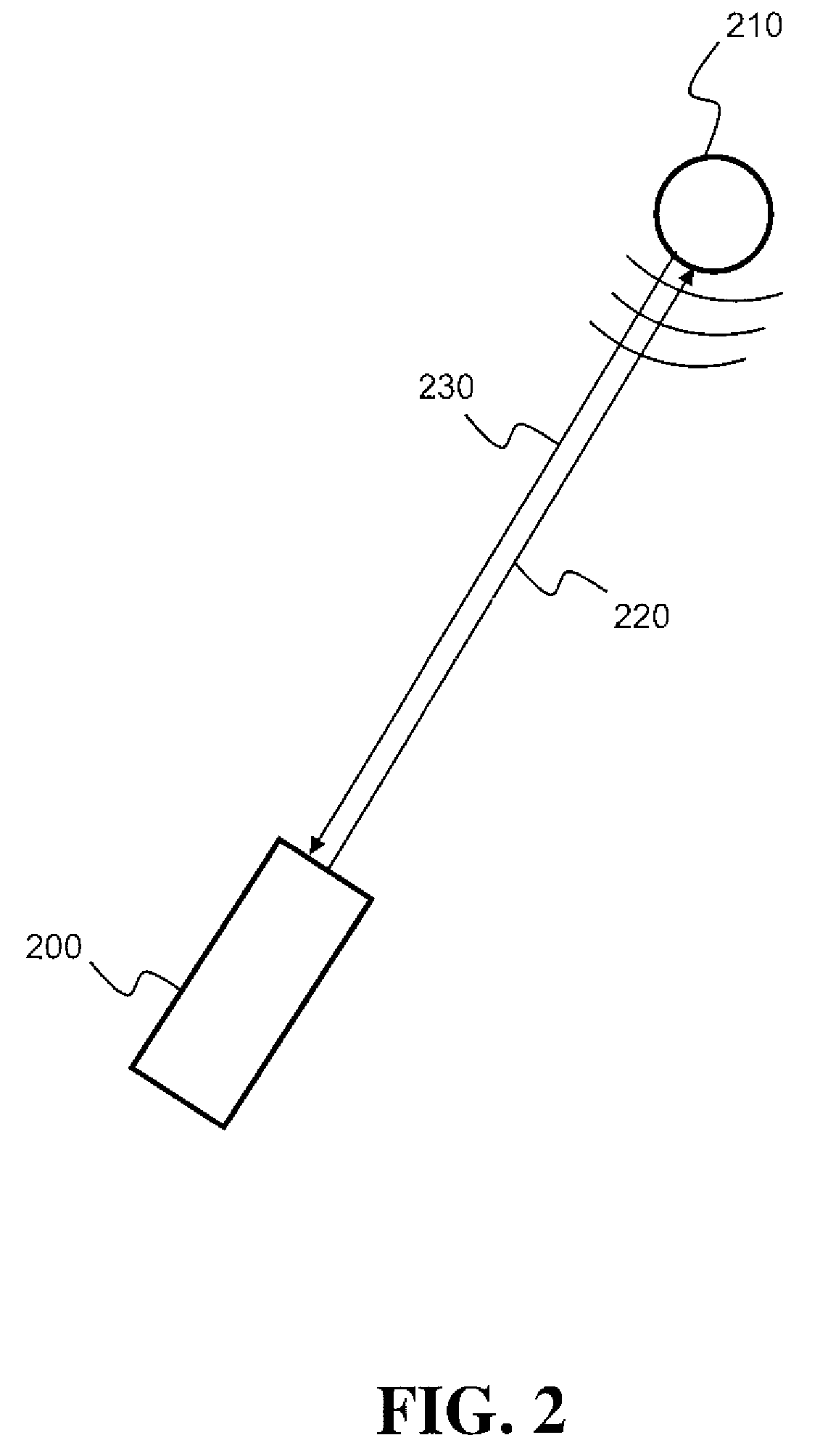
[0024]FIG. 2 shows a schematic diagram of the operational environment according to the present invention. A remote sound sensing apparatus 200 generates an outgoing coherent electromagnetic waves beam 220 that is pointed directly on a vibrations generating sound source 210. Upon hitting the vibrations generating sound source 210, the outgoing coherent electromagnetic waves beam 220 is reflected and returns, with modified physical properties, as a reflected coherent electromagnetic waves beam 230, to the remote sound sensing apparatus 200. When directing the beam at the sound producing source the vast majority of the detected vibrations are related to the sound source. Since the vast majority of the sound producing vibrations related to a sound source are detected, a high degree of separation between the sound source and the ambient is thus achieved. This is due to the fact that the beam is pointed directly at the vibrations producing sound source.

[0025]According to some embodiments ...


PUM


Abstract

An apparatus and a method that achieve physical separation of sound sources by pointing directly a beam of coherent electromagnetic waves (i.e. laser). Analyzing the physical properties of a beam reflected from the vibrations generating sound source enable the reconstruction of the sound signal generated by the sound source, eliminating the noise component added to the original sound signal. In addition, the use of multiple electromagnetic waves beams or a beam that rapidly skips from one sound source to another allows the physical separation of these sound sources. Aiming each beam to a different sound source ensures the independence of the sound signals sources and therefore provides full sources separation.

Description

CROSS-REFERENCE TO RELATED APPLICATIONS[0001]This application claims the benefit under 35 U.S.C. §119(e) of U.S. Provisional Patent Application No. US60 / 841,574 filed Sep. 1, 2006, the content of which is incorporated by reference herein.FIELD OF THE INVENTION[0002]The present invention relates to coherent electromagnetic waves and more specifically, to remote sensing of sound sources using coherent electromagnetic waves.BACKGROUND OF THE INVENTION[0003]Vibrometry is the technical field of measuring vibrations of an object. In remote vibrometry, the vibrations are measured from a distance (aka no-contact vibrometry). One of the common ways to achieve vibrations remote-sensing is by using coherent electromagnetic waves (usually laser) and exploiting their physical properties.[0004]Specifically, the vibrating object acts as a transducer by modifying the properties of the electromagnetic waves that hit it, according to the vibrations, prior to reflecting back the electromagnetic waves....

Claims


Application Information

Patent Timeline
Patent Type & Authority Patents(United States)
IPC IPC(8): G01R33/20H04B10/00
CPCG01H9/00
Inventor BAKISH, TAL
Owner VOCALZOOM SYST
Why Eureka
Try Eureka