Radar system and method

a radar and system technology, applied in the field of radar systems and methods, can solve the problems of short voltage, ineffective coupling, and difficulty in concentrating low frequency radiation on targets

Inactive Publication Date: 2010-08-17
STATE OF ISRAEL MINIST OF AGRI & RURAL DEV AGRI RES ORG (A R O) (VOLCANI CENT)
View PDF11 Cites 45 Cited by
  • Summary
  • Abstract
  • Description
  • Claims
  • Application Information

AI Technical Summary

Benefits of technology

[0030]In one embodiment of the invention, the transmissions from the transmitting antennas are orthogonally polarized one with respect to the other, for eliminating the production of parasitic signal components at the frequency to which the receiving unit is tuned.
[0031]Preferably, the said orthogonal polarization is used for eliminating transmission of signals at the frequency of the receiving unit from any of the transmitting units.
[0034]Preferably, a multi-beam antenna is used at the receiving unit for improving the direction resolution.

Problems solved by technology

In practice, it is difficult to concentrate low frequency radiation on targets, and also the coupling is not efficient (the term “coupling” refers to the ratio between the voltage induced on a component inside the target object and between the intensity of the electromagnetic field surrounding the target object).
On the other hand, parasitic capacitance of the junctions that are part of the object, for example, PN junctions in semiconductor components within the object, metal-semiconductor junctions, or metal-oxide-metal junctions, tend to short the voltage in high frequencies.
Parasitic harmonic signals that are developed in the transmitting unit cause significant problems in distinguishing the searched objects from their surrounding.
Also, metal junctions in the antenna and the transmission lines may create odd harmonics.
These transmitted harmonic frequencies are scattered by all objects and may mask the expected scattered harmonic signals from the non-linear objects, and prevent their detection and investigation.
This is a particular problem when using antennas having strong side-lobes, that cause problems in short-range detection in any type of radar system.

Method used


Image

  • Radar system and method
  • Radar system and method
  • Radar system and method

Examples


example

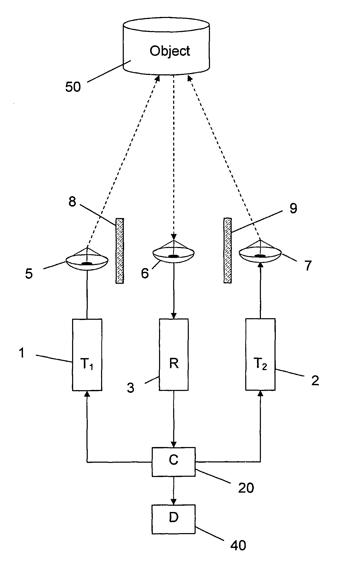
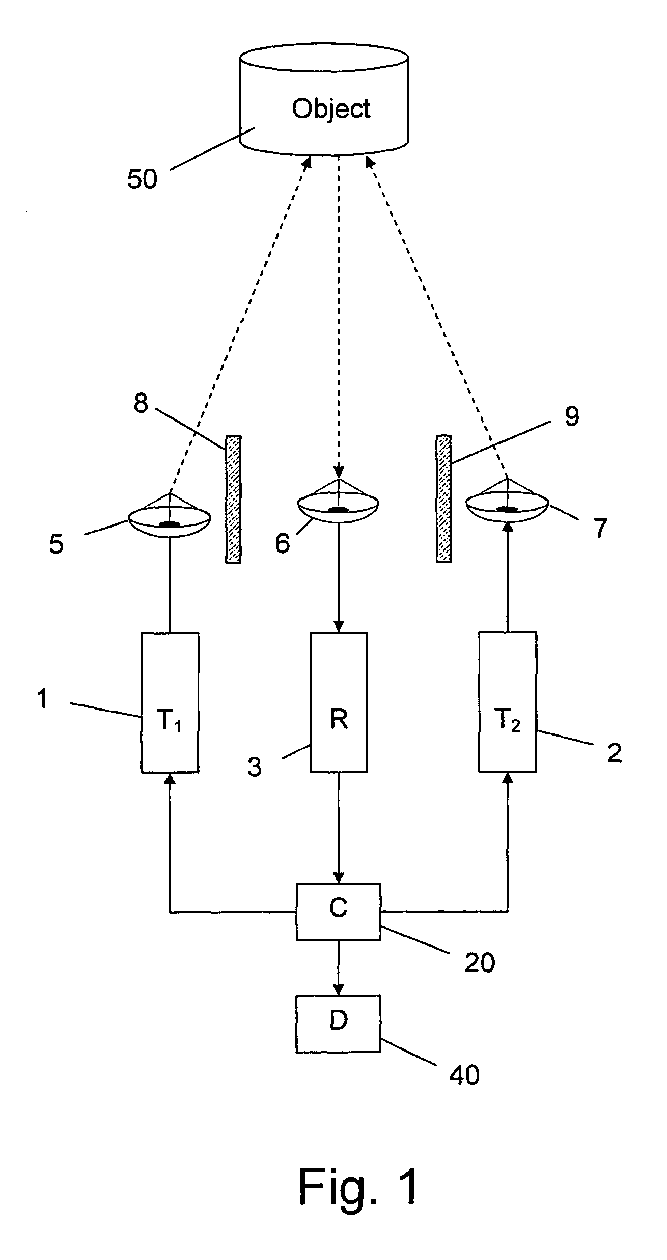
[0069]The following is an example for an efficient frequency selection that provides a system having high sensitivity to the detection of man-made objects. According to this example the transmitting frequencies are f1=2.74 GHz, f2=1.26 GHz, and the reception frequency is fr=4.0 GHz (being the sum f1+f2. In that case the harmonics created at the transmitter 2 are in frequencies 5.48 GHz, 8.22 GHz, 10.96 GHz, . . . etc., and the harmonics created at the transmitter 1 are in the frequencies 2.52 GHz, 3.78 GHz, 5.04 GHz, . . . , etc. It has been demonstrated that in this example the receiving frequency, when properly selected, is remote enough from each of the transmitting frequencies, and / or from any of their harmonics. Therefore, the sensitivity and the ability of the system to distinguish man-made target from their surroundings are improved.

[0070]In one preferred embodiment of the invention, the system of the invention comprises more than two transmitting units, transmitting at more ...


PUM


Abstract

The invention relates to a radar system which comprises: (a) at least two transmitting units for simultaneously, and in synchronization transmitting electromagnetic radiation in distinct frequencies f1, f2, f3 . . . towards a space of interest; and (b) at least one receiving unit tuned to a frequency of nf1+mf2+qf3 . . . , wherein n, m, q . . . being integers not equal to zero, for receiving a non-linear response of said radiation from objects located within the said space of interest.

Description

FIELD OF THE INVENTION[0001]The invention generally relates to a method and system for detecting and locating man-made objects by means of a “harmonic radar” utilizing the objects non-linear response to incident electromagnetic waves.BACKGROUND OF THE INVENTION[0002]Radar systems are widely used for detecting and locating objects. Radar systems usually operate in the UHF (Ultra-High-Frequency) or microwave part of the RF (Radio-Frequency) spectrum, and are used to determine the position and / or movement of an object. There have been developed various types of radar systems, for different purposes and applications.[0003]Any radar system can locate a target by finding its direction and range. The range to an object is determined by calculating the delay between a pulse transmitted by the system, and the consequential receipt of the reflection of said pulse from the object. This determination is based on the known propagation velocity of the pulse c (the speed of light), when the air is...

Claims


Application Information

Patent Timeline
Patent Type & Authority Patents(United States)
IPC IPC(8): G01S7/292G01S13/00
CPCG01S7/292G01S7/41G01S13/24G01S13/88
Inventor SCHNITZER, ITZHAKROSENBERG, AVNERDEUTSCH, ALON
Owner STATE OF ISRAEL MINIST OF AGRI & RURAL DEV AGRI RES ORG (A R O) (VOLCANI CENT)
Why Eureka
Try Eureka