System and method for controlling a multi-string light emitting diode backlighting system for an electronic display

a backlighting system and light-emitting diode technology, applied in the direction of electric variable regulation, process and machine control, instruments, etc., can solve the problems of insufficient idle time, difficult to ignite, and difficult to control the current, so as to achieve stable, stable, and easy to control the current

Active Publication Date: 2010-08-17
ATMEL CORP
View PDF6 Cites 78 Cited by
  • Summary
  • Abstract
  • Description
  • Claims
  • Application Information

AI Technical Summary

Problems solved by technology

The display industry is enthusiastically perusing the use of LEDs as the light source in the backlight technology because CCFLs have many shortcomings: they do not easily ignite in cold temperatures, require adequate idle time to ignite, and require delicate handling.
A challenge in generating sufficient light from multi-string circuits is balancing the current in each string.
Also, a string may contain one or more burnt out or damaged LEDs, causing short circuit conditions.
The challenge in designing multi-string circuits is to ensure that all the light sources are illuminated and that the current in each string is sufficient to bring the light source to the appropriate intensity.
That is inefficient because it generates unneeded light and dissipates more current.

Method used


Image

  • System and method for controlling a multi-string light emitting diode backlighting system for an electronic display
  • System and method for controlling a multi-string light emitting diode backlighting system for an electronic display
  • System and method for controlling a multi-string light emitting diode backlighting system for an electronic display

Examples


Embodiment Construction

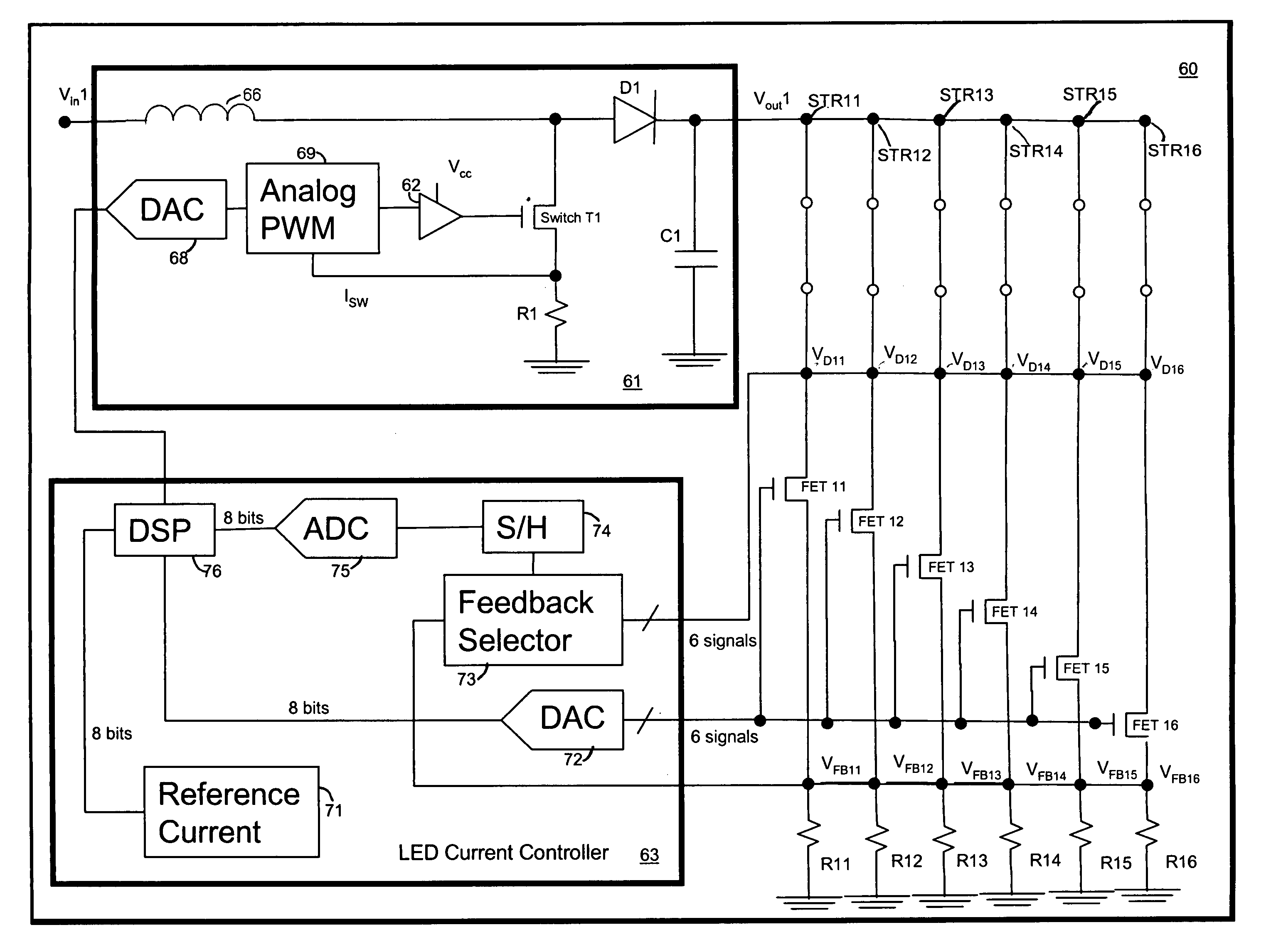
[0022]The present invention relates to power conversion in a multi-string driver circuit for light emitting elements. FIG. 6 shows an exemplary display 60 including the multi-string driver circuit of the present invention for illuminating six strings STR11, STR12, STR13, STR14, STR15 and STR16 of light emitting elements. The strings STR11-STR16 are coupled at one node to the voltage source 61. The voltage source 61 provides a driving voltage VOUT1 to the strings STR11-STR16. In one embodiment, a boost topology circuit is used in the voltage source 61 to provide driving voltage VOUT1 to the six strings STR11-STR16. One of ordinary skill in the art will appreciate that the inductor 66, the diode Dl, the transistor switch T1, the resistor R1 and the capacitor C1 are components of a typical boost topology circuit. The digital to analog converter (DAC) 68, the analog pulse width modulation (PWM) block 69 and the switch driver 62 are used by the LED Current Controller to selectively turn ...


PUM


Abstract

The present invention relates to displays that use LED strings for backlighting. A lead string is provided with continuous drive voltage and the non-lead strings are provided with pulsed drive pulses. The string having the highest forward voltage is selected as the lead string. Feedback information indicative of the currents flowing through the non-lead strings is used to determine the duty cycles of the voltage pulses provided to drive the non-lead strings. The non-lead strings are controlled using pulsed drive voltages to minimize power dissipation in the circuit.

Description

FIELD OF INVENTION[0001]The present invention relates to electronic display technology, and particularly to controlling the light emitting diode (LED) strings of the backlights of electronic displays.BACKGROUND OF THE INVENTION[0002]Backlights are used to illuminate thick and thin film displays including liquid crystal displays (LCDs). LCDs with backlights are used in small displays for cell phones and personal digital assistants (PDA), as well as in large displays for computer monitors and televisions. Typically, the light source for the backlight includes one or more cold cathode fluorescent lamps (CCFLs). The light source for the backlight can also be an incandescent light bulb, an electroluminescent panel (ELP), or one or more hot cathode fluorescent lamps (HCFLs).[0003]The display industry is enthusiastically perusing the use of LEDs as the light source in the backlight technology because CCFLs have many shortcomings: they do not easily ignite in cold temperatures, require adeq...

Claims


Application Information

Patent Timeline
Patent Type & Authority Patents(United States)
IPC IPC(8): G09G3/32H05B44/00
CPCG09G3/3413H05B33/0815H05B33/0827G09G2320/064Y02B20/346H05B45/46Y02B20/30H05B45/38G09G3/36G09G3/32G02F1/133
Inventor S, DILIPTHANDI, GURJITSANTO, HENDRIKVI, KIEN
Owner ATMEL CORP
Why Eureka
Try Eureka