Power unit case configured to house both an engine and a transmission, and power unit including same

a power unit and transmission technology, applied in the direction of machines/engines, drip or splash lubrication, engine starters, etc., can solve the problem of increasing and achieve the effect of reducing the size of the internal combustion engine and enhancing the lubrication of the desired meshing portion

Inactive Publication Date: 2010-08-24
HONDA MOTOR CO LTD
View PDF9 Cites 5 Cited by
  • Summary
  • Abstract
  • Description
  • Claims
  • Application Information

AI Technical Summary

Benefits of technology

[0009]The present invention has been made in view of the above-mentioned problem, and accordingly it is an object of the present invention to provide a power unit case for an internal combustion engine, which makes it possible to enhance the lubrication of a desired meshing portion of a group of transmission gears, while reducing the size of an internal combustion engine.
[0013]Another aspect of the invention is that the main shaft is arranged above the space between the crankshaft and the counter shaft at a position substantially horizontally behind the crankshaft, and the respective axes of the crankshaft, the main shaft, and the counter shaft are positioned at the comers of an acute-angled triangle, thereby reducing the size of the internal combustion engine by a reduction in the front-to-rear width of the unitary case. The gear-ratio selecting mechanism is arranged above the group of transmission gears on the counter shaft whose upper portion rotates toward the meshing portion of the group of transmission gears, and the lubricating projection that projects downward is formed above the transmission gears on the counter shaft and at a location on a ceiling surface inside the transmission case where the gear-ratio selecting mechanism is supported. Accordingly, the lubricating oil that has been thrown upward by the rotation of the group of transmission gears and the like and has adhered onto the ceiling surface of the transmission case travels along the ceiling surface to flow to the lubricating projection, and is then dripped onto the upper portions of the transmission gears on the counter shaft from the lubricating projection and supplied to the meshing portion of the transmission gears as the transmission gears rotate, thereby making it possible to enhance the lubrication of the meshing portion between the transmission gears.
[0014]In the above-described embodiment, the lubricating projection is formed above a combination of transmission gears on the counter shaft which provides a large gear ratio. This provides positive lubrication to the meshing portion of the transmission gears on which a large load acts, enhancing lubrication performance.
[0015]An additional aspect of the invention provides a rib that is oriented in an axial direction formed so as to project downwardly, at a location on the ceiling surface inside the transmission case which is displaced rearwardly from a position vertically above the main shaft. Accordingly, the lubricating oil that has been thrown upward by the rotation of the group of gears on the main shaft is temporarily received by the rib, and is dripped onto the group of transmission gears and supplied to the meshing portion between groups of transmission gears. Further, the lubricating oil that has scattered off and adhered onto the ceiling surface due to the centrifugal force of the rotation of the groups of transmission gears is collected to the lubricating projection and dripped onto the transmission gears, thereby enabling efficient lubrication of both the groups of transmission gears that are meshing with each other in multiple stages.
[0016]Another aspect of the invention is that the gear-ratio selecting mechanism is a shift fork shaft that is positioned close to the mutually meshing groups of transmission gears of both the main shaft and the counter shaft. Therefore, the lubricating projection, at a location on the ceiling surface of the transmission case where the shift fork shaft, is supported in a position close to the group of transmission gears on the counter shaft, thereby enabling efficient supply of lubricating oil to the transmission gears.

Problems solved by technology

Although the arrangement of the main shaft and the counter shaft side by side in the front-to-rear direction allows lubricating oil to be dripped to the meshing portion of transmission gears from above, the front-to-rear width of the unitary case becomes large, resulting in an increase in the size of the internal combustion engine.

Method used


Image

  • Power unit case configured to house both an engine and a transmission, and power unit including same
  • Power unit case configured to house both an engine and a transmission, and power unit including same
  • Power unit case configured to house both an engine and a transmission, and power unit including same

Examples


Embodiment Construction

[0028]A selected illustrative embodiment of the invention will now be described in some detail, with reference to the drawings. It should be understood that only structures considered necessary for clarifying the present invention are described herein. Other conventional structures, and those of ancillary and auxiliary components of the system, are assumed to be known and understood by those skilled in the art.

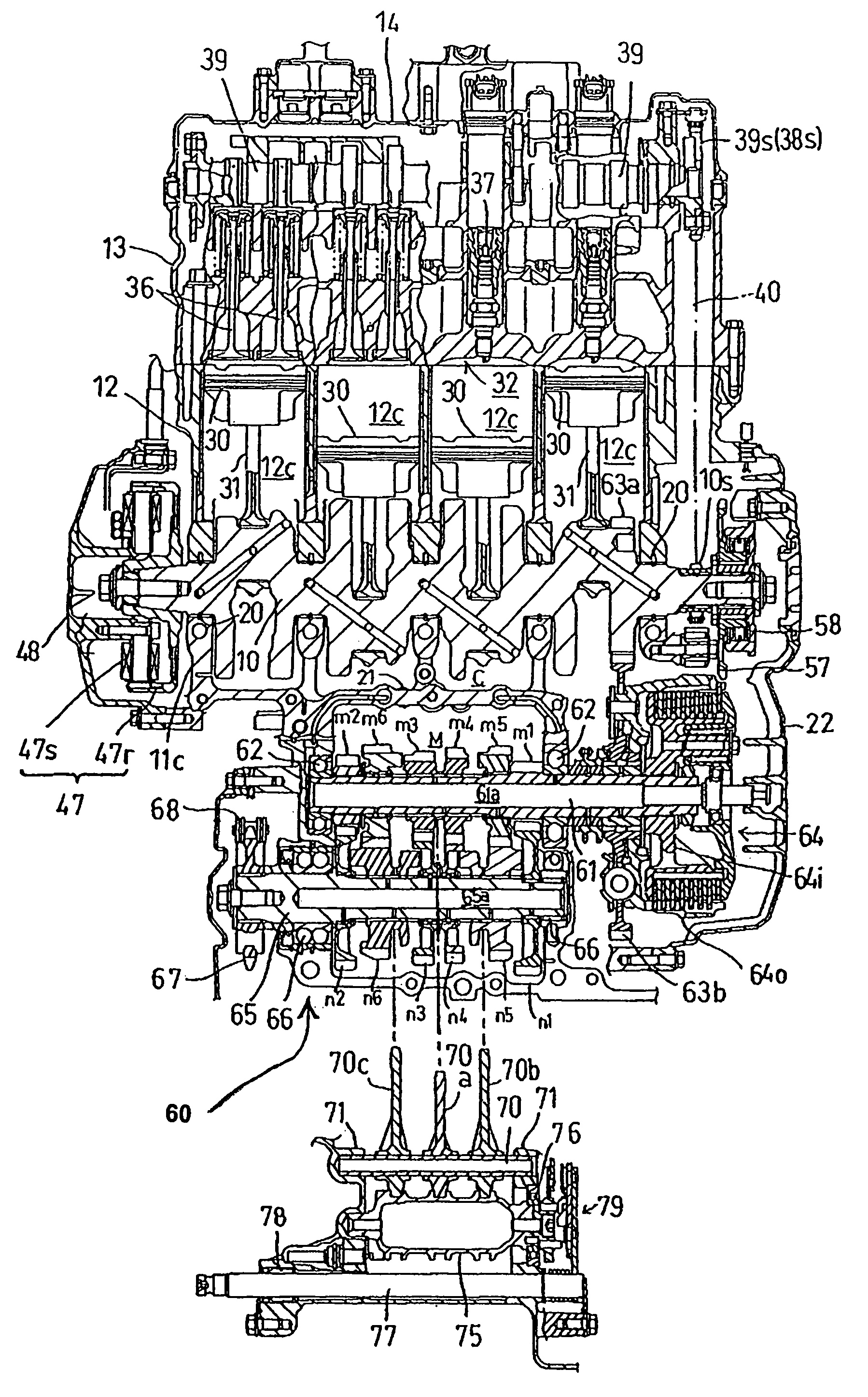
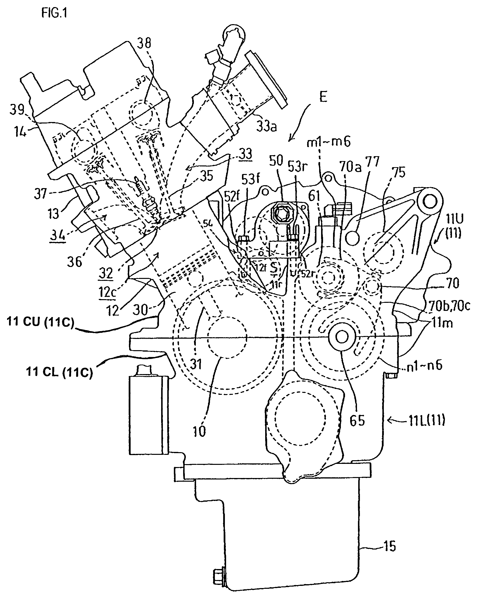
[0029]An internal combustion engine E according to this embodiment is a four-cylinder, water-cooled four-stroke internal combustion engine in which the four cylinders are arranged in an in-line series. The internal combustion engine E is horizontally mounted in a motorcycle with a crankshaft 10 oriented in the left-to-right direction with respect to the advance direction of the vehicle.

[0030]It should be noted that in this specification, relative positional terms such as front, rear, left and right are considered from a vantage point of a driver seated on the motorcycle and fa...


PUM


Abstract

A power unit case for a power unit, including an internal combustion engine and a transmission, makes it possible to enhance the lubrication of a desired meshing portion of a group of transmission gears, while reducing the size of the engine. In the power unit case, a main shaft is arranged above a space between a crankshaft and a counter shaft arranged at a position substantially horizontally behind the crankshaft. A gear-ratio selecting member is arranged above a group of transmission gears on the counter shaft whose upper portion rotates toward a meshing portion between groups of transmission gears, and a lubricating projection that projects downwardly is formed in the transmission case above each of the transmission gears on the counter shaft and at a location on a ceiling surface of the transmission case where the gear-ratio selecting member is supported.

Description

CROSS-REFERENCE TO RELATED APPLICATIONS[0001]The present invention claims priority under 35 USC §119 based on Japanese patent application No. 2006-234032, filed on Aug. 30, 2006. The entire disclosure of this priority document, including specification, claims, and drawings is incorporated by reference herein.BACKGROUND OF THE INVENTION[0002]1. Technical Field of the Invention[0003]The present invention relates to a power unit case for a power unit including an internal combustion engine and a transmission. In the power unit case, a crankcase and a transmission case are formed integrally together as a power unit case. The present invention also relates to a power unit incorporating an engine and a transmission within the described power unit case.[0004]2. Background Art[0005]With regard to internal combustion engines, used as a power source for vehicles, including a unitary case in which the rotation of a crankshaft in a crankcase is transmitted to the rotation of a main shaft in a t...

Claims


Application Information

Patent Timeline
Patent Type & Authority Patents(United States)
IPC IPC(8): F16H57/02F16H61/00F16H57/04F01M9/06F16N11/06F16N7/02F01M9/08F16H57/023
CPCF02N15/006F16H57/02F16H57/0421Y10T74/2186F16H2057/0203F16H2057/02043F16H2057/02086F16H63/18
Inventor MUKOUHARA, HODAKAHAYASHI, TENSEISHIOZAKI, EIKO
Owner HONDA MOTOR CO LTD
Why Eureka
Try Eureka