Method and apparatus for monitoring and controlling conveyor position

a technology of conveyors and position monitoring, applied in the direction of conveyor control devices, conveyor parts, transportation and packaging, etc., can solve the problems of difficult measurement of the amount of belt in the belt take-up or belt storage section, difficult control of the motion of enormously heavy belts, and difficult repair of (es) after a deceleration slowing down period

Inactive Publication Date: 2010-08-24
BAKER CAPITAL LIMITED A PENNSYLVANIA
View PDF14 Cites 41 Cited by
  • Summary
  • Abstract
  • Description
  • Claims
  • Application Information

AI Technical Summary

Benefits of technology

[0015]In another embodiment, the above counter means provides a substantially continuous visual display of the remaining belt footage beyond the power-off point (POP) which the event site has

Problems solved by technology

For example, in long coal mines where the conveyor extends many thousands of feet, e.g., 3,000 or more, in low light and cramped conditions, the damage site may be detected on the fast moving conveyor, e.g., 10-15 mph or more, but controlling the motion of the enormously heavy belt such that the (ES) can be brought to a stop at a convenient repair station after a deceleration slowing down period is very difficult.
The massive momentum of the belt, especially when loaded, prevents any rapid stopping of the belt and over running of the (ES) beyond the repair station (TS) often dictates that more than one complete and time consuming lap of the lo

Method used


Image

  • Method and apparatus for monitoring and controlling conveyor position
  • Method and apparatus for monitoring and controlling conveyor position
  • Method and apparatus for monitoring and controlling conveyor position

Examples


Embodiment Construction

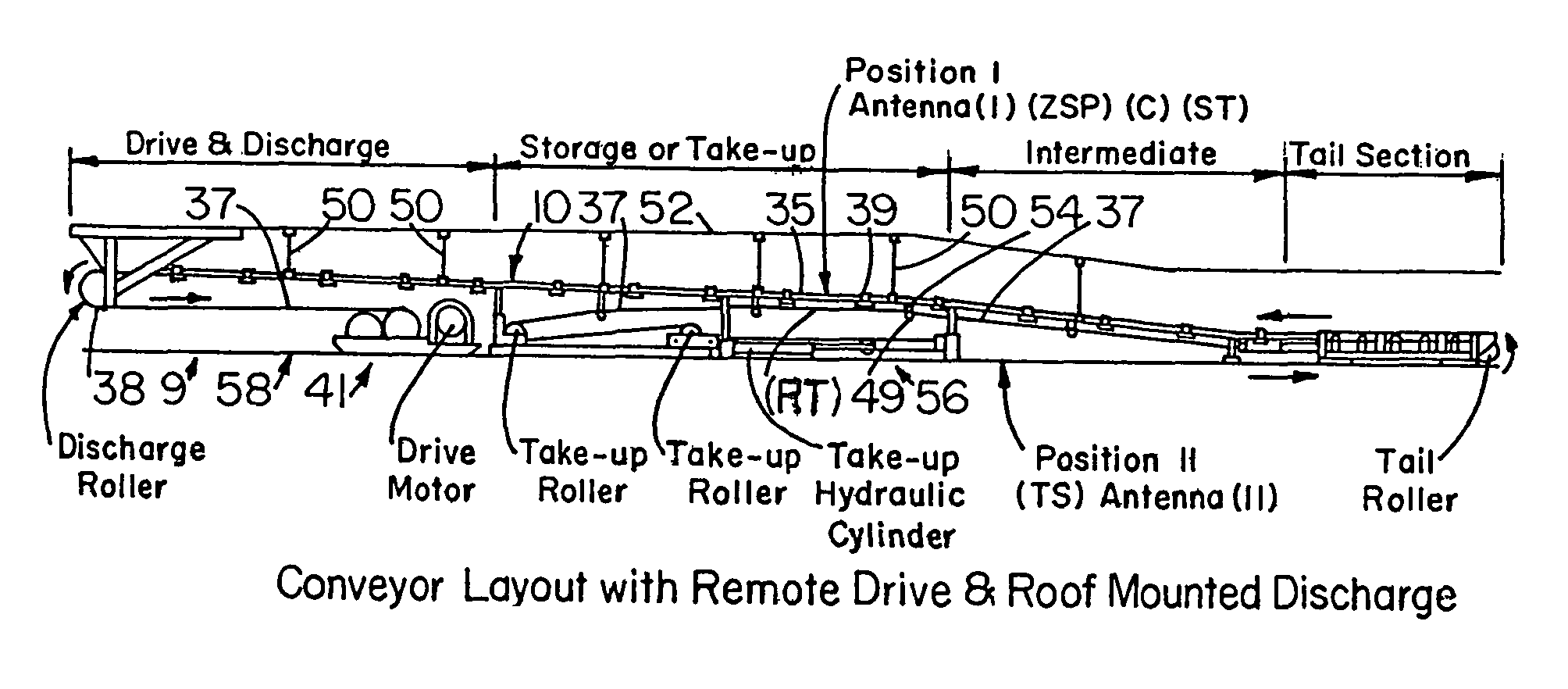
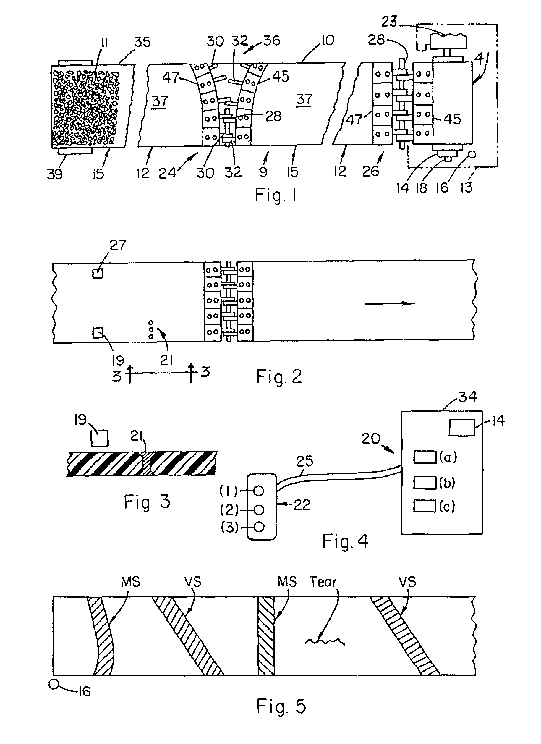
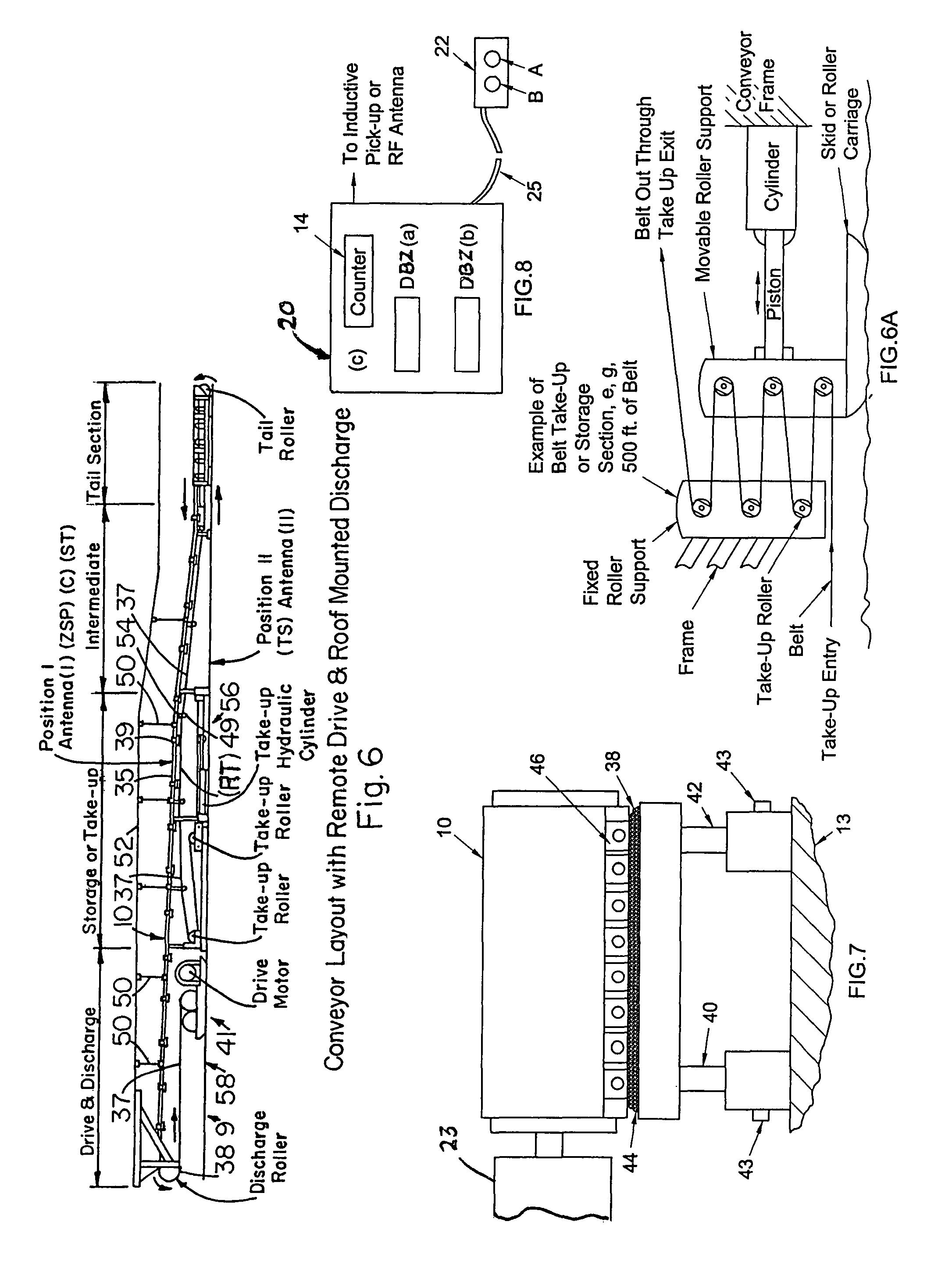
[0031]The following glossary will assist in understanding the present “BPU” system:[0032](CP) cycle point[0033]ZSP zero set point (prescribed belt cycle travel footage reading at which counter is reset to zero (ZSP) or other prescribed reading)[0034]ES event site[0035]DBZ (C) reading at (SST) at time of (ES) spotting[0036]TS target station or repair station (RS)[0037]C counter means[0038]ESS event site signal[0039]MS mechanical splice[0040]VS vulcanized splice[0041]CR counter reading[0042]CPL cycle point footage of RF (RT) Tag from (C).[0043]LD lag distance[0044]RSBZ distance of RS beyond ZSP[0045]BD belt drift footage[0046]BTR belt take-up run footage (from Ant. I to Ant. II)[0047]POP power-off point[0048]STP stop point of belt[0049]RFID radio frequency identification tag[0050]SST spotter station[0051]CR counter[0052]RT reset tag[0053]ESS event site signal[0054]B button[0055]RSBZ known footage distance of (TS) beyond the (ZSP)[0056]POFI footage from (ES) spotting at (SST) to (POP)[...


PUM


Abstract

A Belt Positioning Unit “BPU” operation which in use for facilitating the maintenance of long, heavy conveyor belts of conveyor systems comprises the steps of (a) monitoring a conveyor belt for event sites, (b) spotting an event site and logging into a computer (1), sufficient data from which the computer determines and records the footage location of the event site on the belt, (2) belt drift footage data, and (3) take up belt footage data, and (c) using said data to control operational aspects of the conveyor system components, e.g., belt speed, drive motor power-off point (POP), or belt scraper pressure which affect the maintenance or condition of said event site.

Description

[0001]This is a complete application for Applicants Provisional 60 / 838,052 filed Aug. 16, 2006 of same title, and Applicant hereby claims the benefit and priority of said Provisional.BACKGROUND OF THE INVENTION[0002]1. Field[0003]Conveyor system transport equipment such as belts, chains, cable, and rope, particularly conveyor belts of the lengthy and endless type used to transport material such as coal, minerals, products or the like over long distances typically comprise a drive roller means, a tail roller means, and a belt means, typically in 500-1000 ft., sections for long heavy duty belts, with their ends connected (spliced) to make the belt endless. Such belts are used to convey thousands of tons of material or product per hour. These belts range from one or two feet in width up to seven feet or more in width and are up to three or more miles in total length with several sections of belt spliced end to end with riveted metal splices or cured rubber splices, or other such means....

Claims


Application Information

Patent Timeline
IPC IPC(8): B65G43/00
CPCB65G43/02
Inventor TRAVIS, TONNY D.
Owner BAKER CAPITAL LIMITED A PENNSYLVANIA
Why Eureka
Try Eureka