Methods of and sludge collector with adjacent opposed oppositely-moving blades for moving sludge in a basin

a technology of sludge collector and basin, which is applied in the direction of liquid displacement, separation process, transportation and packaging, etc., can solve the problems of reducing the efficiency of the desired movement, increasing the cost and weight, and the basin present a problem, and achieves high resistance to both tension and compressive for

Active Publication Date: 2010-08-24
MEURER RES
View PDF129 Cites 8 Cited by
  • Summary
  • Abstract
  • Description
  • Claims
  • Application Information

AI Technical Summary

Benefits of technology

[0016]Briefly, embodiments of the present invention meet all of the above needs by providing a way of providing a sludge collector system and methods that reduce the tendency of the sludge to be moved in the return direction. Further, embodiments of the present invention meet all of the above needs by providing a way for such system and methods to avoid the need, in actual commercial practice, for the use of any structural drive member other than the one net (or a main frame) that supports (or carries) the blades themselves. Further, embodiments of the present invention meet all of the above needs by providing a way in actual commercial embodiments to eliminate the above-described extra structural drive member that has high resistance to both tension and compressive forces exerted parallel to the directions 34 and 36. Embodiments of the present invention further meet all of the above needs by providing a way for the individual scrapers, or blades, to have a configuration that is manufacturable in a low-cost manner.
[0017]Embodiments of the present invention may meet all of the above needs by providing two blades configured to be adjacent to each other; with a drive configured to simultaneously move each of the adjacent blades relative to an outlet of a basin, wherein the drive configuration is to provide the simultaneous movement of each blade in opposition to the other blade. The embodiments may configure the drive with a first support for one blade and a second support for the other blade, the supports being separate from each other. The embodiments may further configure the drive with at least one direction-reversal unit connected between the first and second supports.
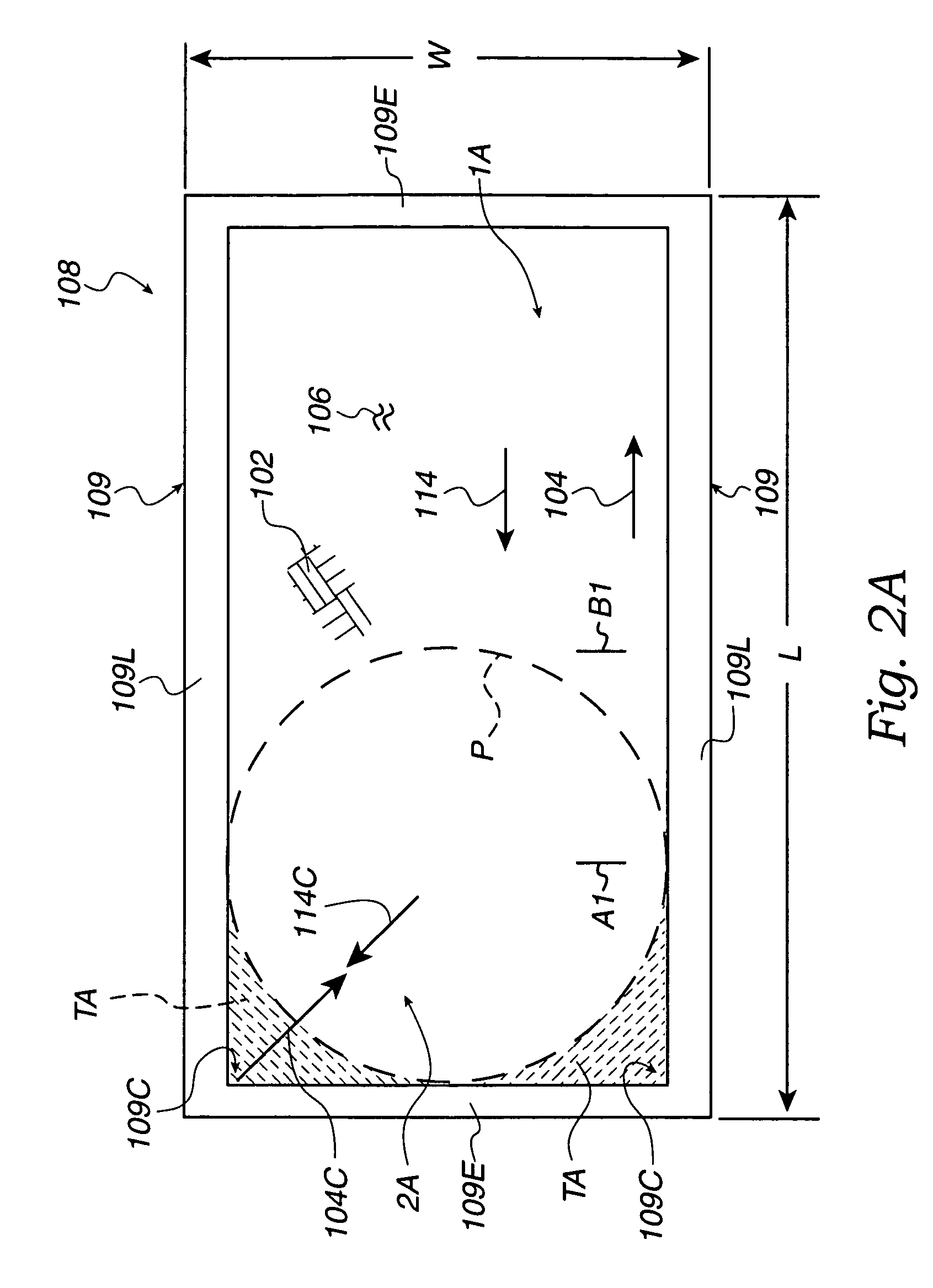
[0018]Embodiments of the present invention may meet all of the above needs by also providing a basin configured with adjacent first and second walls intersecting the floor and intersecting each other to define a corner of the basin, where a first location of blade movement is next to the walls, and a blade stop location is away from the walls, and a second location is further away from the walls than the blade stop location. One blade is further configured with characteristics of flexibility and an extended shape so that when the one blade is in the first location the one blade is flexed and extends into the corner next to both of the walls. The drive may be further configured to move the one blade from the blade stop location to the first location and cause the one blade to flex and extend into the corner so that the one blade is next to both walls and causes material near the walls to move from the walls and spill over the one blade and toward the blade stop location. The drive may be further configured to move the one blade from the first location to the blade stop location at the same time as the other blade is moved toward the one blade so that the material spills over the other blade and toward the second location.
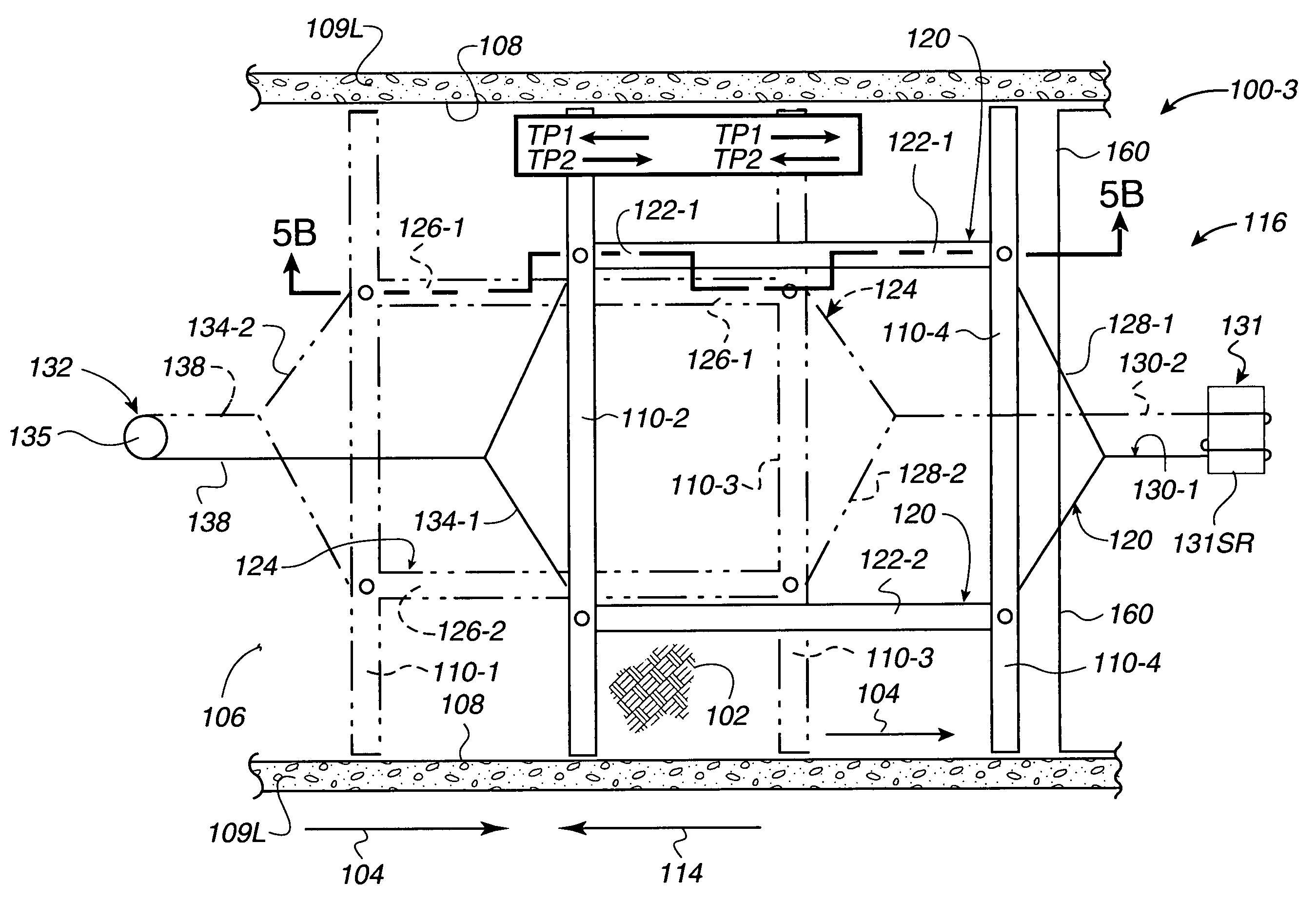
[0022]The way embodiments of the present invention avoid the need, in actual commercial practice, for the use of any structural drive member other than the separate rails that carry the respective blades themselves, is by applying only tension, or pull, forces to each of separate rails, and by connecting one rail drive to each of the separate rails so that a pull force applied to one rail in one (e.g., forward, or “to”) direction is applied by that rail (via the one rail drive) to the other rail in the opposite (e.g., return, or “fro”) direction. In this manner, each rail may be fabricated from material having minimum, or reduced, structural characteristics. Such material need have a characteristic of high resistance only to tension forces, and need have low (or no) resistance to compressive forces. This characteristic greatly reduces the cost of the sludge collection system, yet each rail is structurally sufficient to carry and drive the blades through the sludge as the respective rail moves across the bottom of the basin. As a result of the new combination of the low-cost blades with the significantly improved configuration of the drive, during the respective “to” and “fro” movements the blades resist those tension forces and the drive does not apply compressive forces to the rails. Thus, the present invention eliminates the above-described prior extra structural drive member that has high resistance to both tension and compressive forces.
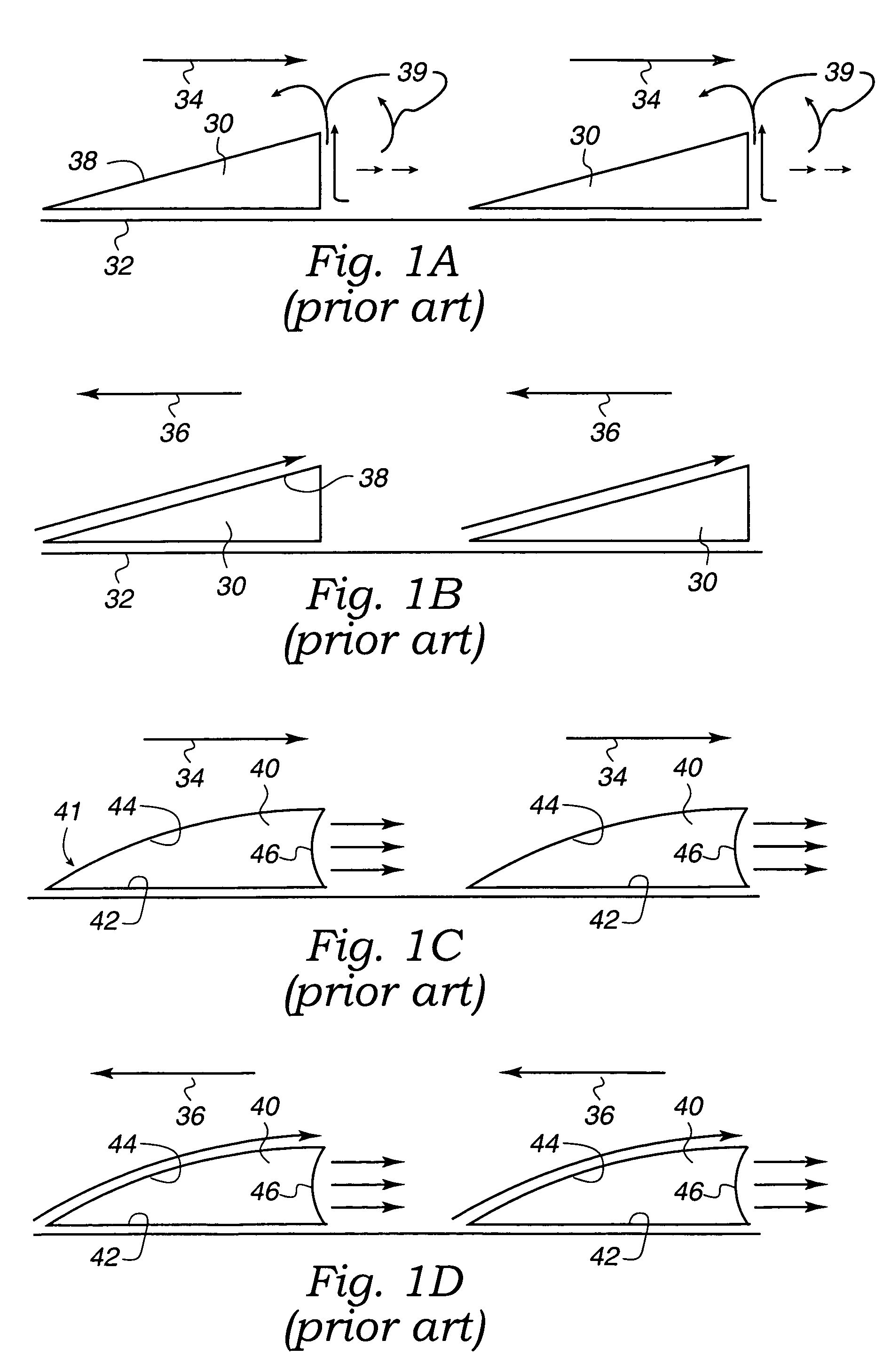
[0023]The way of providing scrapers, or blades, that have a low-cost configuration is by providing many low-cost blade embodiments, such as one using all-curved blades of standard configuration (such as a circular cross-section), or one using the blades shown in FIGS. 1A and 1B, and in each case of low-cost blades using the low-cost blades in a new combination with a significantly improved configuration of the drive for those low-cost blades.

Problems solved by technology

Because the flocculators are designed to circulate liquid and materials, rather than to promote settling of the materials, the materials that inadvertently collect at the bottom of the basin present a problem.
The undesired movement in the return direction reduces the efficiency of the desired movement in the “to” (or forward) direction.
Such an extra structural member has increased the cost and weight of those commercial embodiments, and the extra weight increases the required energy (e.g., electrical power and thus operating cost) to move the scrapers.
As noted, this structure and movement results in undesired movement of the sludge in the return direction 36 due to all of the scrapers moving together (at the same time in the return direction 36).
This further reduces the efficiency of the overall operations because the reintroduced particles have to be again settled and then removed from the basin.
The requirement for higher power for this pushing of all blades together at the same time, and the increased weight of the extra compressive member that enables pushing instead of pulling the structure, result in the motor used for moving the system being more costly than a lower-power motor.
Also, such extra compressive member makes the net 32 less compliant with respect to uneven floors of the basin, which in turn results in higher costs to initially provide a smoother floor for the basin (e.g., of concrete) and higher repair costs in not damaging the smoother floor of the basin during repair.
Lastly, if a generally-triangular cross-section blade is to be used, there is additional cost to manufacture the convex and concave shapes of the scrapers 40.

Method used


Image

  • Methods of and sludge collector with adjacent opposed oppositely-moving blades for moving sludge in a basin
  • Methods of and sludge collector with adjacent opposed oppositely-moving blades for moving sludge in a basin
  • Methods of and sludge collector with adjacent opposed oppositely-moving blades for moving sludge in a basin

Examples


Embodiment Construction

[0038]Referring now to FIGS. 2A and 2B, embodiments 100 of the present invention may move material 102 in a first (or “to”) direction (see arrow 104) relative to a bottom (or floor) 106 of a basin 108. The first direction is a desired direction of material movement. The basin 108 may be a container or tank provided with walls, e.g., four walls 109. The walls 109 may include two walls, a side wall 109L and an end wall 109E, that are adjacent to each other and that define a corner 109C (FIG. 2A) of the basin 108. The corner 109C is where the two walls 109L and 109E intersect, and may extend vertically, for example.

[0039]The basin 108 may contain apparatus (not shown) in which the materials 102 are collected. For example, the materials 102 may be collected by being separated from liquids (not shown) by plate or tube settlers (not shown) that promote settling of the material 102 to the bottom 106 of the basin 108. The apparatus may also be a flocculator (not shown) in which the material...


PUM

PropertyMeasurementUnit
distanceaaaaaaaaaa
distanceaaaaaaaaaa
depthaaaaaaaaaa

Abstract

Apparatus and methods provide individual blades driven by drives configured to reduce a tendency of sludge to be moved in an undesired return direction. Drive configurations apply “pull” and “pull” forces that only pull on tensile structures, avoiding a need in actual commercial practice for use of extra structural drive members having high resistance to both tension and compressive forces exerted parallel to a sludge movement direction. Each of two separate tensile structures carries one blade, or a separate set of blades, with blade(s) of one structure adjacent to, and alternating with, blade(s) of the other structure. Embodiments move sludge from a corner of a basin and across a floor of the basin. The reduced tendency of sludge movement in the return direction results from moving one tensile structure and blade(s) in the sludge movement direction as the other tensile structure and adjacent opposed blade(s) move in the return direction.

Description

BACKGROUND[0001]1. Field[0002]The present invention relates generally to removing materials from liquids, and more particularly to adjacent opposed, oppositely moving blades for, and methods of, moving sludge in a sludge collection basin for removal of the sludge from the basin.[0003]2. Description of the Related Art[0004]In the past, containers (e.g., basins or tanks) have been provided to house apparatus in which materials are collected. The materials may have any of a wide variety of compositions, and generally consist of pieces of the materials that move under the force of gravity to the bottom (or floor) of the basin (“settleable-particles”). For example, in municipal waste water systems, the materials may be formerly biologically-active waste materials that are no longer biologically-active, and that are in the form of the settleable-particles.[0005]For ease of description, materials within the wide range of compositions and that consist of the settleable-particles, are referr...

Claims


Application Information

Patent Timeline
Patent Type & Authority Patents(United States)
IPC IPC(8): B01D21/18
CPCB01D21/18
Inventor BRAUCH, JOSEPH KARLMEURER, CHARLES LONNIE
Owner MEURER RES
Why Eureka
Try Eureka