Hybrid vehicle and method of assembling same

a hybrid vehicle and vehicle technology, applied in the field of hybrid vehicles, can solve the problems of limited space and prohibitive modification of conventional vehicles, conventional vehicles may not achieve the fuel efficiency of a hybrid vehicle, and cannot benefit from the reduced cost of operating the vehicl

Active Publication Date: 2010-08-24
GENERAL ELECTRIC CO
View PDF60 Cites 48 Cited by
  • Summary
  • Abstract
  • Description
  • Claims
  • Application Information

AI Technical Summary

Problems solved by technology

Because of the increased complexity of known hybrid vehicles, the vehicles are originally manufactured such that the electric drive system is formed integrally with the engine system.
Therefore, it may be cost prohibitive and space limited to modify a conventional vehicle to include an electric drive system that is coupled between the engine and transmission.
As a result, conventional vehicles may not achieve the fuel efficiency of a hybrid vehicle and thus may also not benefit from the reduced costs of operating the vehicle.

Method used


Image

  • Hybrid vehicle and method of assembling same
  • Hybrid vehicle and method of assembling same
  • Hybrid vehicle and method of assembling same

Examples


first embodiment

[0024]FIG. 5 is a simple schematic illustration of precharge and interface circuit 80. As shown in FIG. 5, circuit 80 includes a pre-charge resistor 90 and a pre-charge contactor 92 that are coupled in parallel with a main contactor 94. During operation, the main contactor 94 is enabled or closed when the interface control circuit 80 detects that the voltage difference across the main contactor 94 is at or below a determined voltage value. Optionally, the main contactor 94 is closed after the pre-charge contactor 92 has been closed for a determined length of time. In both of the above pre-charge embodiments, after the main contactor 94 is closed, the interface control circuit 80 commands the pre-charge contactor 92 to open.

second embodiment

[0025]FIG. 6 is a simple schematic illustration of precharge and interface circuit 80. As shown in FIG. 6, circuit 80 includes the main contactor 94 and a constant current circuit 96 that is coupled in parallel with main contactor 94. Optionally, the voltage of the first energy storage 66 is decoupled from the DC input of the inverter 68 using the concept described in U.S. Pat. No. 5,373,195.

[0026]During operation, after the initial vehicle startup, the ultracapacitor 82 and the first energy storage unit 66, e.g. a battery, are electrically connected via the main contactor 94. During a first mode of operation when the vehicle is accelerating, power is supplied to the electric motor drive inverter 68 and thus the electrical device functioning as the motor 30 by a combination of both energy storage units 66 and 82 coupled in a substantially parallel arrangement. The power split between the two energy storage units 66 and 82 is determined by the battery's open circuit voltage and assoc...


PUM


Abstract

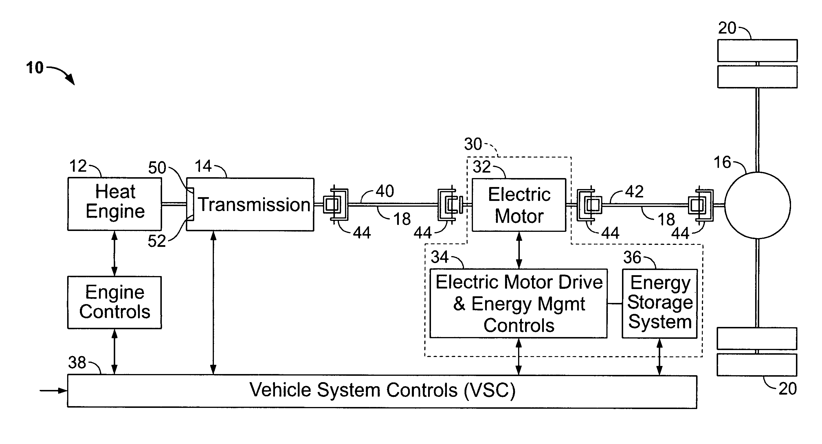
A parallel hybrid vehicle includes a heat engine, a transmission including an input and output, and an electrical device. The transmission input is coupled to the engine and the transmission output is coupled to the electrical device such that substantially all of the torque generated by the heat engine is channeled through the transmission to the electrical device, and a differential, the electrical device coupled to the differential such that during a first mode of operation the electrical device functions as a motor to receive substantially all the torque generated by the engine through the transmission, and such that during a second mode of operation the electric device functions as a generator to receive substantially all the torque generated by the vehicle through the differential.

Description

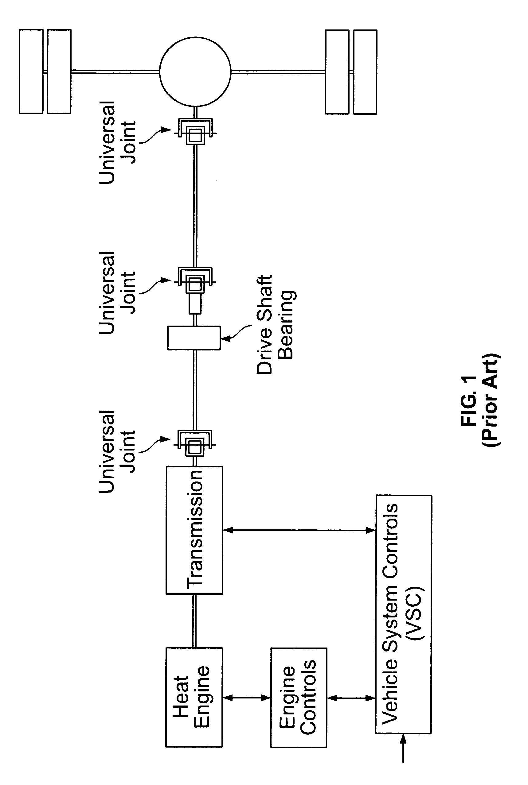
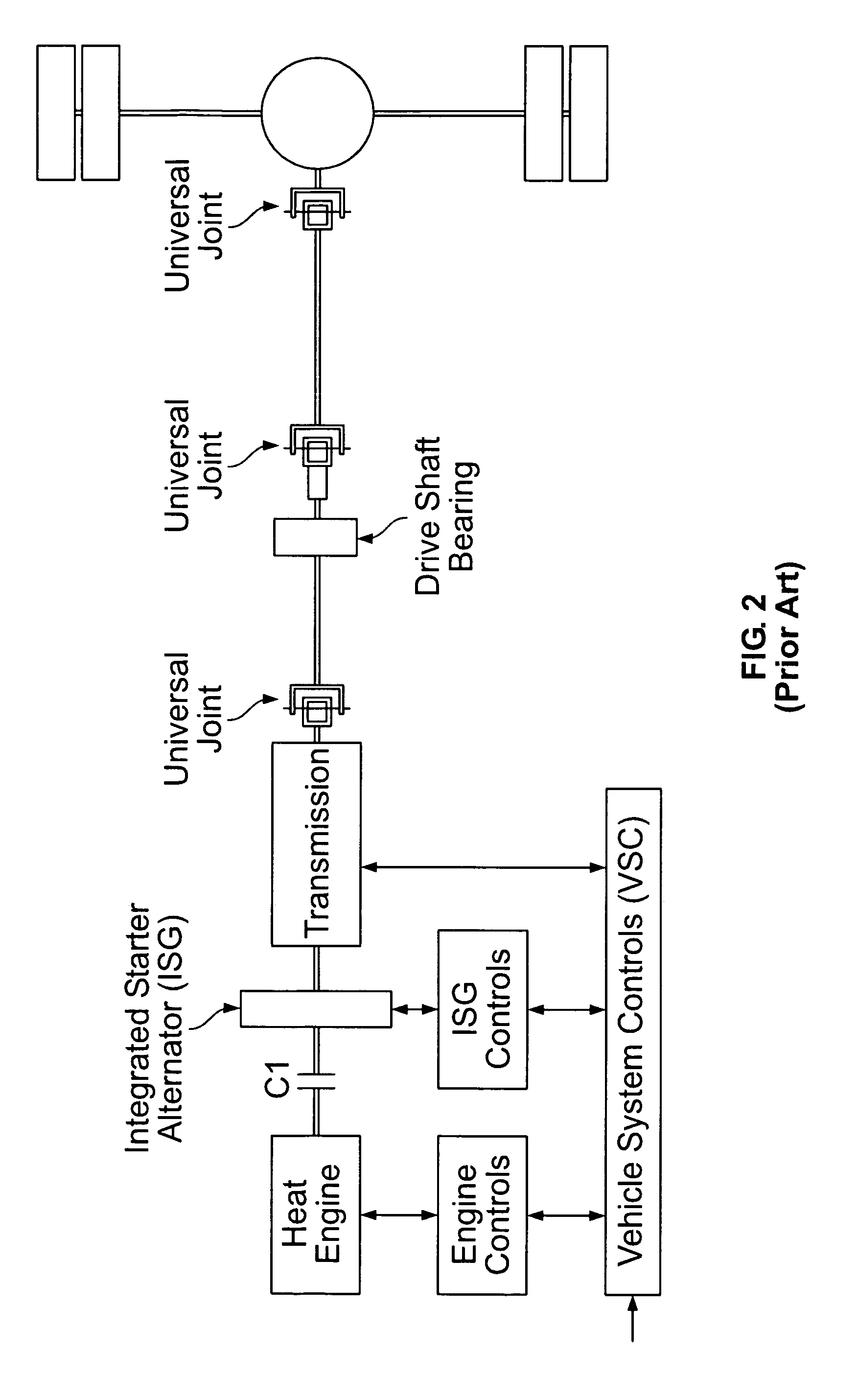
BACKGROUND OF THE INVENTION[0001]This invention relates generally to a vehicle, and more specifically to a hybrid vehicle, and a method of retrofitting a known vehicle to achieve a hybrid vehicle.[0002]FIG. 1 illustrates a known power train for a conventional vehicle, such as may be used in a Heavy Duty Truck or Bus. FIG. 2 illustrates a parallel hybrid vehicle that includes a known electric drive system that is coupled between an engine and a transmission. The electric drive system in this configuration is often referred to as an Integral Starter Alternator (ISG) or Mild Hybrid, and provides the functions of engine cranking, supplying electrical torque during the vehicle launch acceleration and hill climbing, and may also be used as an alternator to charge the vehicle Starting Lighting, and Ignition (SLI) battery.[0003]As known, hybrid vehicles offer many advantages the foremost being fuel efficiency. However, hybrid vehicles also include additional components such as the electric ...

Claims


Application Information

Patent Timeline
Patent Type & Authority Patents(United States)
IPC IPC(8): F16H3/72B60K6/48B60K6/547B60L50/15
CPCB60K6/26B60K6/547B60L3/0046B60L11/14B60K6/48Y02T10/70B60L2210/40B60L2240/423B60L2240/443B60L2270/20Y02T10/6221Y02T10/642Y02T10/7077Y02T10/7241B60L2200/26Y10T477/23B60L50/16B60L58/18Y02T10/62Y02T10/64Y02T10/72Y02T10/7072
Inventor KING, ROBERT DEANSALASOO, LEMBIT
Owner GENERAL ELECTRIC CO
Why Eureka
Try Eureka