Electromagnetic tracking method and system

a tracking method and electromagnetic technology, applied in the field of electromagnetic tracking methods and systems, can solve the problems of inaccurate magnitude and direction of magnetic field sensed by complementary em sensors, distortion of magnetic field emitted by em sensors, and error in the determined location of devices

Active Publication Date: 2010-08-24
STRYKER EURO OPERATIONS HLDG LLC
View PDF38 Cites 35 Cited by
  • Summary
  • Abstract
  • Description
  • Claims
  • Application Information

AI Technical Summary

Problems solved by technology

However, as will be appreciated, the presence of field distorting objects in or near the magnetic field may cause distortions of the magnetic field emitted from the EM sensors.
As a result, the magnitude and direction of the magnetic field sensed by the complementary EM sensor may be inaccurate.
Unless compensated for, or significantly reduced, these distortions and inaccuracies may produce an error in the determined location of the device.
The eddy currents may produce additional electromagnetic fields that distort the electromagnetic field originally generated by the EM sensor, thereby creating errors in the determined position and orientation of the complementary EM sensor.
Although, methods are known to map and compensate for the distortions, if the distortions become too significant, mapping may not be capable of compensating for the distortions.

Method used


Image

  • Electromagnetic tracking method and system
  • Electromagnetic tracking method and system
  • Electromagnetic tracking method and system

Examples


Embodiment Construction

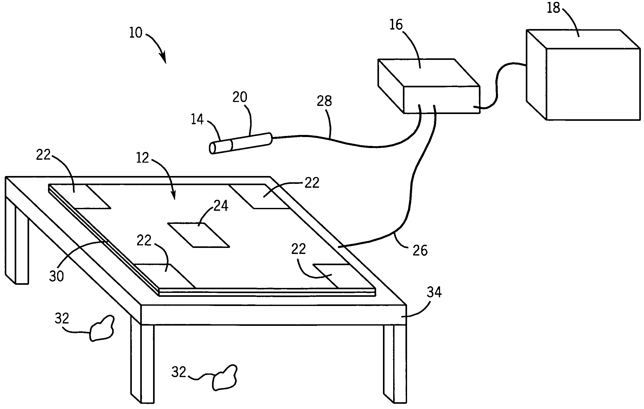
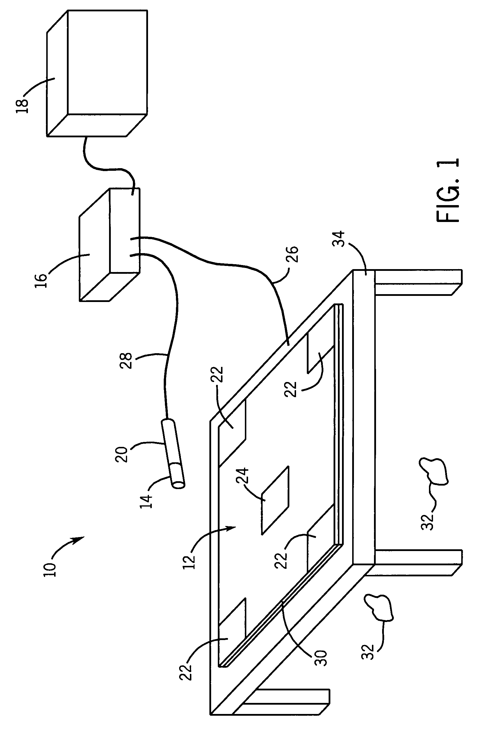
[0029]Referring now to FIG. 1, a tracking system 10 in accordance with one embodiment of the present technique is illustrated. The tracking system 10 may generally include multiple tracking components. As depicted, the tracking components may include an electromagnetic (EM) coil arrangement 12, at least one complementary EM sensor 14, a processor 16 and a user interface 18. The at least one complementary EM sensor 14 may be coupled to at least one instrument 20.

[0030]In the illustrated embodiment, the EM coil arrangement 12 comprises a plurality of EM sensors 22 and at least one center EM sensor 24. Generally, the EM sensors 22 and at least one center EM sensor 24 may be formed from magnetic dipoles (e.g., coils, current loops, or electromagnets) capable of producing a dipole magnetic field when a current is applied across them. In some embodiments, the EM sensors (such as the plurality of EM sensors 22 and the at least one center EM sensor 24) may employ industry-standard coil arch...


PUM

PropertyMeasurementUnit
thickaaaaaaaaaa
thickaaaaaaaaaa
tilt angleaaaaaaaaaa

Abstract

Provided is an electromagnetic coil arrangement comprising a set of electromagnetic sensors at fixed locations with respect to each other, each of the electromagnetic sensors comprising a planar coil coupled to a conductive layer, the planar coil comprising non-concentric rings. Further, provided is an electromagnetic tracking system, comprising an electromagnetic coil arrangement, at least one complementary electromagnetic sensor and a processor configured to process a signal comprising data indicative of a mutual inductance between the at least one complementary electromagnetic sensor and each of the set of the electromagnetic sensors of the electromagnetic coil arrangement. Also, provided are a method of tracking and a method of manufacturing an electromagnetic coil arrangement.

Description

BACKGROUND[0001]This disclosure relates generally to tracking systems that use magnetic fields to determine positions and orientations of an object, such as systems used for tracking instruments and devices during surgical interventions and other medical procedures. More particularly, the present disclosure relates to a system and method to more accurately determine position and orientation of an object.[0002]Tracking systems have been used in various industries and applications to provide position information relating to objects. For example, electromagnetic tracking may be useful in aviation applications, motion sensing applications, and medical applications. In medical applications, tracking systems have been used to provide an operator (e.g., a physician) with information to assist in the precise and rapid positioning of a medical device located in or near a patient's body. In general, an image may be displayed on a monitor to provide positioning information to an operator. The ...

Claims


Application Information

Patent Timeline
Patent Type & Authority Patents(United States)
IPC IPC(8): G01B7/14H01F5/00
CPCG01B7/004H01F5/003H01F7/20
Inventor ANDERSON, PETER TRANEUS
Owner STRYKER EURO OPERATIONS HLDG LLC
Why Eureka
Try Eureka