
System and method for accelerated MR imaging

a technology of accelerated mr imaging and imaging system, applied in the field of mri (magnetic resonance imaging) methods and apparatus, can solve the problems of limited time resolution and the need for extensive setup of parallel excitation approaches

Active Publication Date: 2010-08-24
GENERAL ELECTRIC CO
View PDF13 Cites 3 Cited by
  • Summary
  • Abstract
  • Description
  • Claims
  • Application Information

AI Technical Summary

Benefits of technology

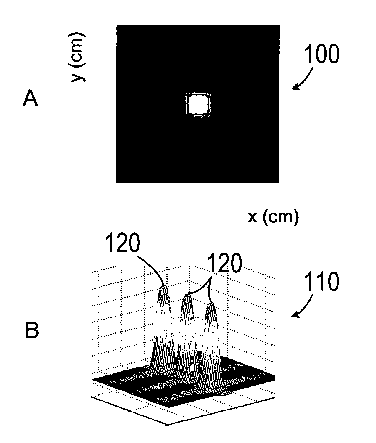
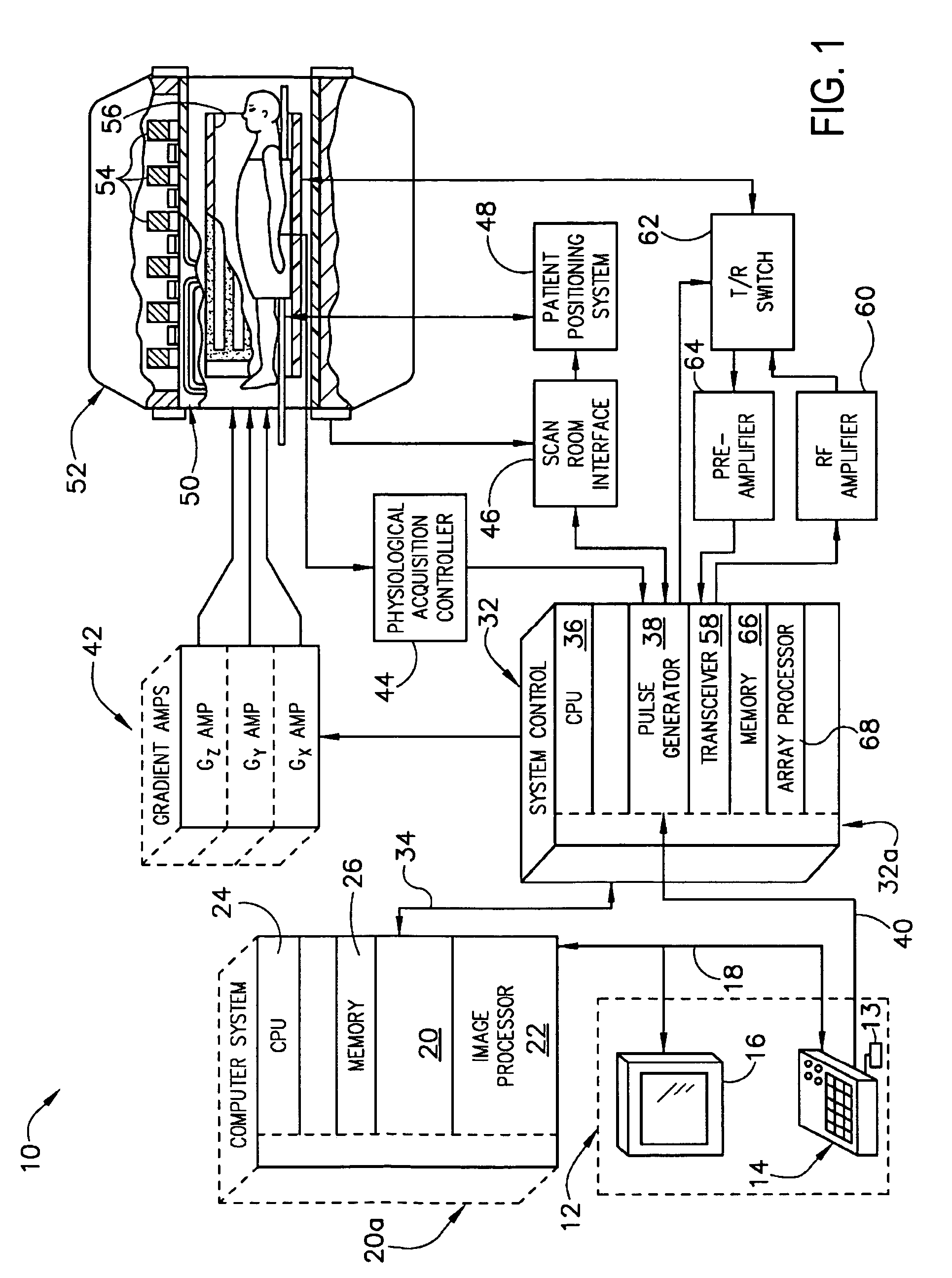
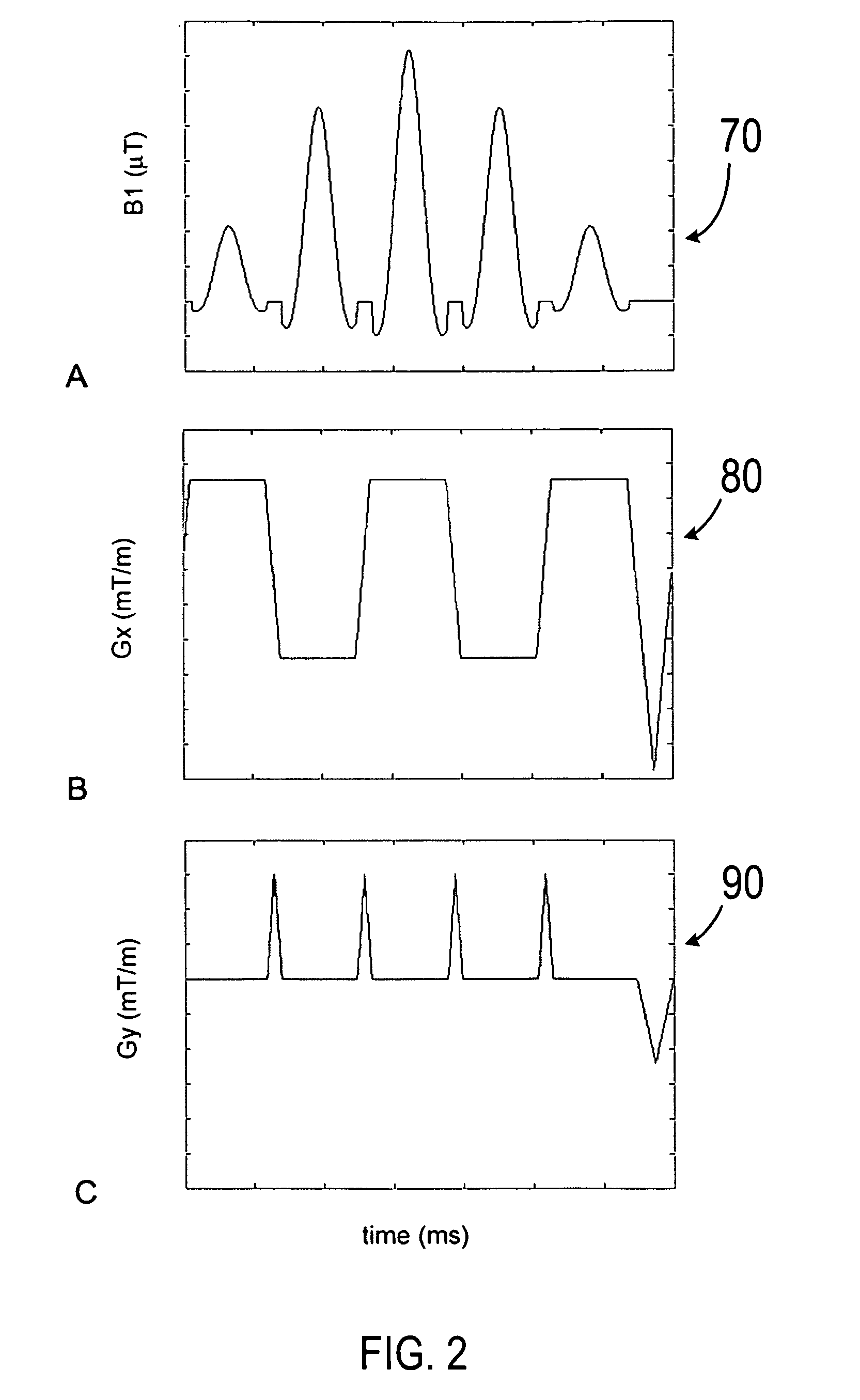
"The present invention provides a system and method for accelerated MR imaging that overcomes the drawbacks of conventional methods. The invention involves using an MRI apparatus with multiple gradient coils and an RF transceiver system to transmit RF signals to an RF coil assembly to acquire MR images. The system also uses an under-sampled echo-planar excitation trajectory to excite multiple pencil regions and simultaneously acquire MR signals on multiple channels from the RF receiver array. The acquired MR signals are then separated contributions from the multiple pencil regions using parallel imaging reconstruction to produce an MR M-mode image of the object. The technical effects of the invention include faster MRI imaging, improved image quality, and reduced image blurring."

Problems solved by technology

One major problem with the abovementioned techniques is that the time resolution is limited by the extensive duration of the 2D excitation pulses.
However, the parallel excitation approach requires extensive setup and there are currently only a few scanners capable of this.

Method used


Image

  • System and method for accelerated MR imaging
  • System and method for accelerated MR imaging
  • System and method for accelerated MR imaging

Examples


Embodiment Construction

[0020]In the following, reference is made to embodiments of the invention. However, it should be understood that the invention is not limited to specific described embodiments. Instead, any combination of the following features and elements, whether related to different embodiments or not, is contemplated to implement and practice the invention. Furthermore, in various embodiments the invention provides numerous advantages over the prior art. However, although embodiments of the invention may achieve advantages over other possible solutions and / or over the prior art, whether or not a particular advantage is achieved by a given embodiment is not limiting of the invention. Thus, the following aspects, features, embodiments and advantages are merely illustrative and are not considered elements or limitations of the appended claims except where explicitly recited in a claim(s). Likewise, reference to “the invention” shall not be construed as a generalization of any inventive subject mat...


PUM


Abstract

A system and method for accelerated MR imaging includes a magnetic resonance imaging (MRI) system having a plurality of gradient coils positioned about a bore of a magnet, and an RF transceiver system and an RF switch controlled by a pulse module to transmit RF signals to an RF coil assembly comprising at least one RF transmit coil and comprising multiple coils to acquire MR images. The MRI apparatus also has a computer programmed to excite multiple pencil regions by use of an under-sampled echo-planar excitation trajectory and acquire MR signals simultaneously on multiple channels of the RF coil assembly. The computer is also programmed to separate contributions from the various multiple pencil regions by use of parallel imaging reconstruction.

Description

BACKGROUND OF THE INVENTION[0001]The present invention relates to MRI (Magnetic Resonance Imaging) methods and apparatus. More specifically, the invention relates to methods of shortening 2D (two-dimensional) excitation pulses for MRI and MRI apparatus using the same.[0002]When a substance such as human tissue is subjected to a uniform magnetic field (polarizing field B0), the individual magnetic moments of the spins in the tissue attempt to align with this polarizing field, but precess about it in random order at their characteristic Larmor frequency. If the substance, or tissue, is subjected to a magnetic field (excitation field B1) which is in the x-y plane and which is near the Larmor frequency, the net aligned moment, or “longitudinal magnetization”, MZ, may be rotated, or “tipped”, into the x-y plane to produce a net transverse magnetic moment Mt. A signal is emitted by the excited spins after the excitation signal B1 is terminated and this signal may be received and processed...

Claims


Application Information

Patent Timeline
Patent Type & Authority Patents(United States)
IPC IPC(8): G01V3/00
CPCG01R33/3415G01R33/4833G01R33/4836G01R33/5611
Inventor HARDY, CHRISTOPHER JUDSONMARINELLI, LUCA
Owner GENERAL ELECTRIC CO
Learn More