
Bowtie deflector cavity for a linear beam device

a linear beam and deflector cavity technology, applied in the field of resonant cavity, can solve the problems of limiting the application of very high-energy beams, e-field depression, and a considerable reduction of interaction impedance, and achieve the effect of superior resonant cavity design and short beam transit tim

Inactive Publication Date: 2010-08-24
L 3 COMM CORP
View PDF8 Cites 0 Cited by
  • Summary
  • Abstract
  • Description
  • Claims
  • Application Information

AI Technical Summary

Benefits of technology

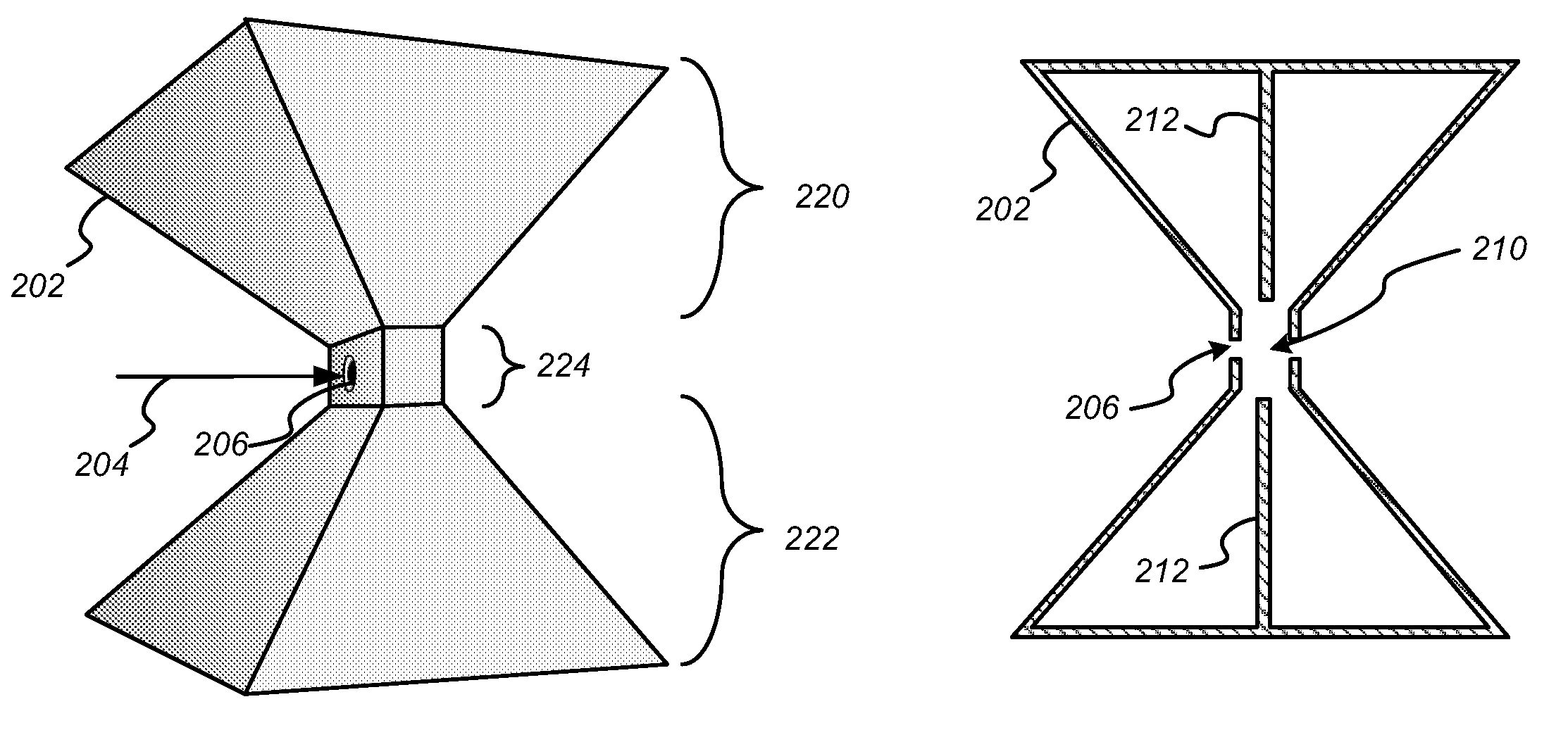
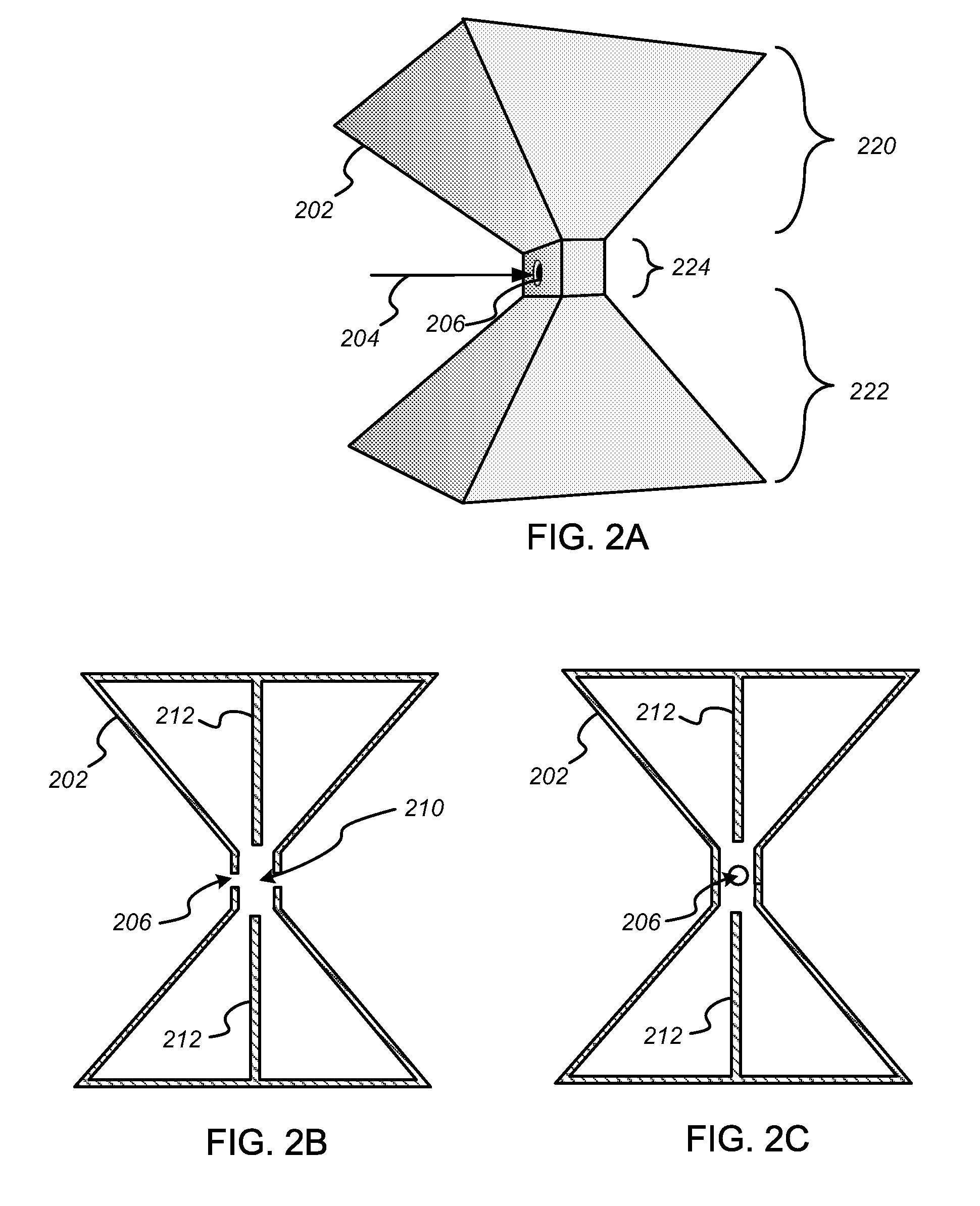
[0008]The invention provides a superior resonant cavity design for deflecting an electron beam. The cavity has a tapered shape that enables a short beam transit time while supporting transverse-electric-field modes within the cavity.
[0012]A single bowtie cavity in accordance with the present invention may be used in a system that generates an electron beam in order to bend the electron beam in one dimension. To bend an electron beam in two dimensions, two bowtie cavities may be arranged to align the drift regions such that the electron beam will pass through the drift regions of both the first and second bowtie cavities. The two cavities are oriented such that the lobes of the two cavities do not extend in a parallel direction. For convenience, the two cavities may be arranged to be orthogonal to one another so that each cavity may bend the electron beam in an independent direction. However, as long as the two cavities are not parallel to each other, it is possible to control the trajectory of the electron beam in two dimensions.

Problems solved by technology

This limits its application to very high-energy beams with electron velocities great enough to cross the cavity in less than half a cycle.
At lower energies, re-entrant drift tube noses are required to limit the transit time, resulting in E-field depression and a considerable reduction in interaction impedance.

Method used


Image

  • Bowtie deflector cavity for a linear beam device
  • Bowtie deflector cavity for a linear beam device
  • Bowtie deflector cavity for a linear beam device

Examples


Embodiment Construction

[0026]The invention provides a resonant cavity for a linear beam device that deflects an electron beam. Unlike a conventional resonant cavity, a cavity in accordance with the present invention provides a large cavity volume capable of supporting a resonant electromagnetic field while at the same time providing a narrow drift region across which the electron beam propagates. In the detailed description that follows, like element numerals are used to indicate like elements appearing in one or more of the figures.

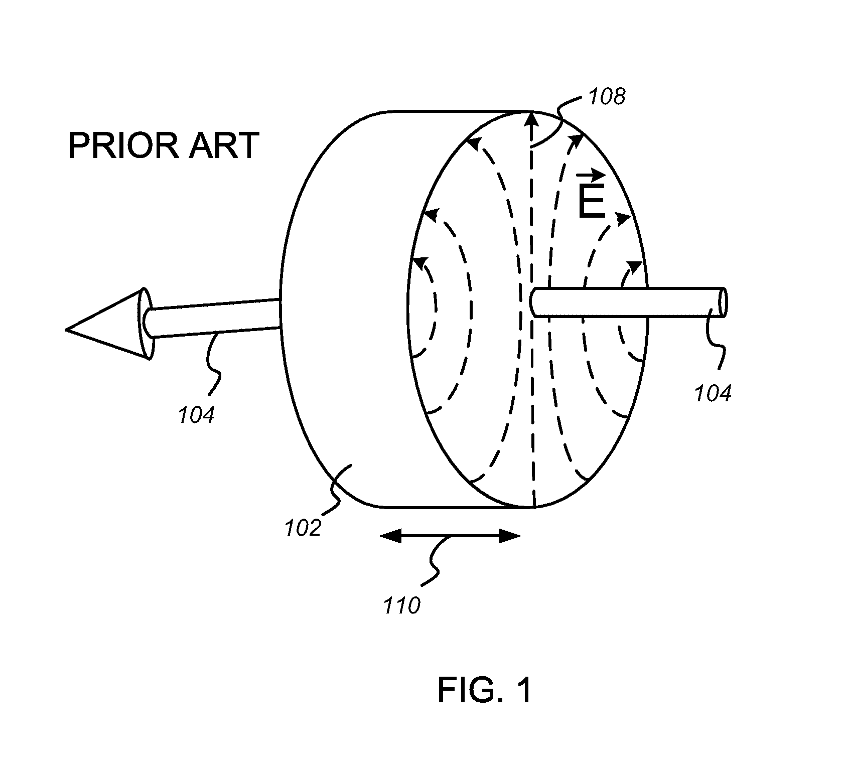
[0027]A conventional resonant cavity, such as the pillbox cavity pictured in FIG. 1, is sized to support a resonant transverse-electric-field mode, shown schematically at 108. An electron beam 104 enters one side of the cavity 102, is bent by the electric field 108, and emerges from the other side. The path length of the electron beam through the cavity 102 is roughly equal to the cylinder height 110 of the cavity. This height must be kept large enough to support the resonant ...


PUM


Abstract

A resonant cavity with a bowtie shape supports an electromagnetic field used to deflect the trajectory of an electron beam passing through the cavity. The short transit time of the beam across the gap maintains the cavity fields at near-optimal phase, improving interaction efficiency even for relatively low-energy beams. High interaction impedance ensures good drive-power-to-deflection conversion efficiency. The uniform field achieved across the gap enforces uniform deflection across the beam profile to maintain beam quality. Multiple bowtie cavities can be arranged to allow arbitrary two-dimensional deflections.

Description

RELATED APPLICATION DATA[0001]This application claims the benefit, pursuant to 35 U.S.C. §119(e), of U.S. Provisional Application Ser. No. 60 / 913,181, filed Apr. 20, 2007.BACKGROUND OF THE INVENTION[0002]1. Field of the Invention[0003]The present invention relates to linear beam devices, and more particularly, to a resonant cavity arranged to deflect an electron beam.[0004]2. Description of Related Art[0005]Many applications require the deflection of an electron beam. For example, a cathode ray tube includes an evacuated region containing an electron gun that is a source of an electron beam, and a fluorescent screen. When the electron beam strikes the fluorescent screen, light is emitted from the point of impact. The electron beam may be deflected and modulated by the application of electromagnetic fields in such a way that an image is made to appear on the screen.[0006]When deflected at very high frequencies, an electron beam can be used to produce electromagnetic radiation. It is ...

Claims


Application Information

Patent Timeline
Patent Type & Authority Patents(United States)
IPC IPC(8): H03F3/54H03F3/60
CPCH01J21/06H01J23/207H01J25/04
Inventor KIRSHNER, MARK FREDERICKKOWALCZYK, RICHARD DONALDWILSEN, CRAIG BISSET
Owner L 3 COMM CORP
Learn More