Low-loss interface

a low-loss, interface technology, applied in the field of interfaces, can solve the problems of dielectric loss, signal/energy loss, and portion of signal loss

Active Publication Date: 2010-08-24
VIASAT INC
View PDF36 Cites 223 Cited by
  • Summary
  • Abstract
  • Description
  • Claims
  • Application Information

AI Technical Summary

Problems solved by technology

Transitioning microwave signals from one mode to another or interfacing to another medium is “lossy.” The signal / energy is lost to radiation, metal losses, dielectric losses, and mismatch losses.
By being lossy, a portion of the signal is lost as it travels through the circuits, wires, and other mediums.
Transitions at microwave frequencies are particularly difficult and lossy.
At microwave frequencies metal losses become greater due to reduced skin depth and increased sensitivity to surface roughness.
Apart from materials being lossier at microwave frequencies, the design of the transitions and interfaces is more difficult.
It is difficult to control or predict phase at microwave frequencies.
This leads to greater mismatch losses.
One exemplary circuit that generates and transports microwaves is a “monolithic microwave integrated circuit” or “MMIC.” Lost signal waves are unusable and decrease the efficiency of a MMIC as the signal strength decreases due to loss.
Generally, the higher the frequency of the microwave, the more lossy the transmission medium and more inefficient the circuit.
In certain applications, even signal losses that reduce the signal small amounts, such as 1 / 10 of a decibel, may result in a significant performance loss.
Unfortunately, signal loss is still problematic with certain waves because the connection or interface between the circuit generating the energy waves and the waveguide can be lossy itself.
This is especially an obstacle with MMIC generated microwaves.
Moreover, impedance miss-matches also cause signal losses.
However, current impendence matching interfaces between an integrated circuit such as a MMIC and a waveguide still have an unacceptable amount of loss.
While effective, interfaces that require dielectric materials are more expensive to produce and require a greater number or parts or materials as a dielectric must be included.
Use of a dielectric also reduces the interface's efficiency as the dielectric also has an associated loss.

Method used


Image

  • Low-loss interface
  • Low-loss interface
  • Low-loss interface

Examples


Embodiment Construction

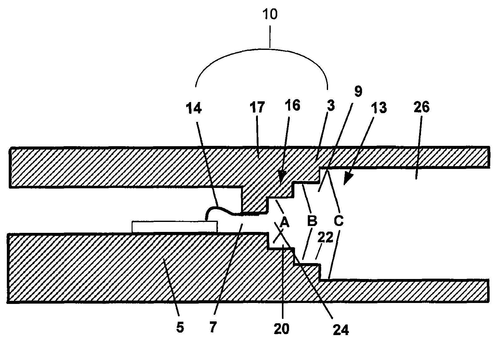
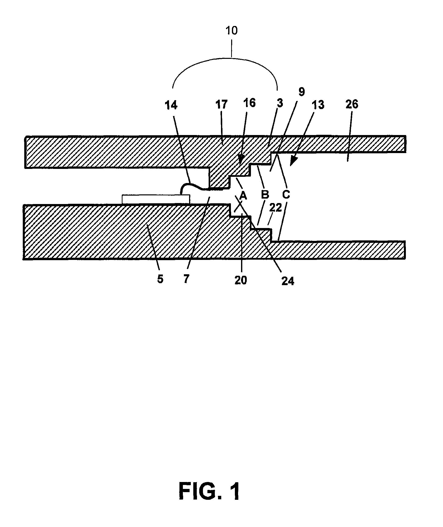
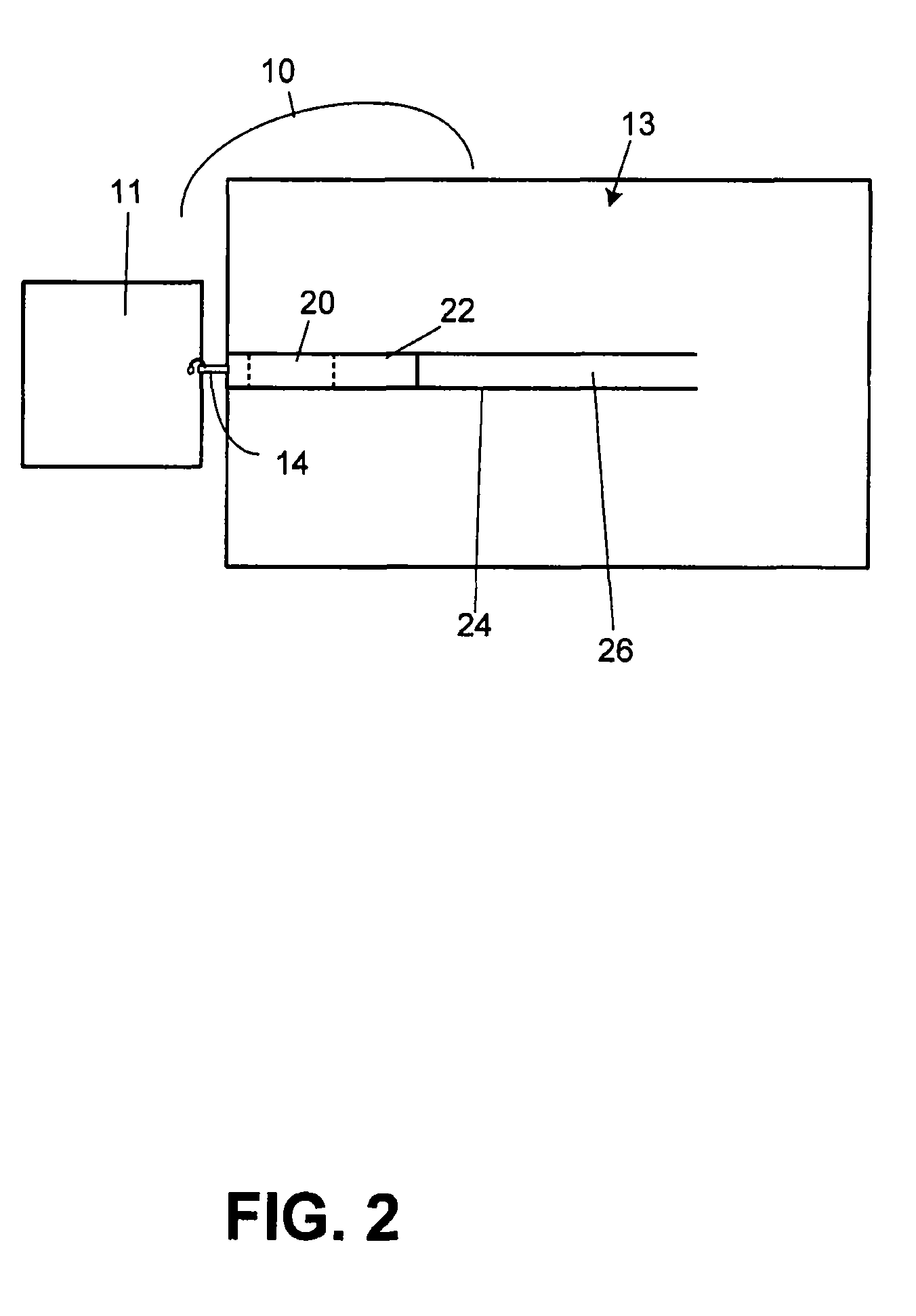
[0014]In accordance with one aspect of the present invention, an interface for connecting an integrated circuit to an energy transmission device such as a waveguide is disclosed. Throughout, the interface will be referred to as interface 10.

[0015]With reference to FIGS. 1-3, and in accordance with an exemplary embodiment of the present invention, an interface 10 is provided between an integrated circuit 11 and an energy transmission device 13. For example, interface 10 may be provided between a MMIC and a waveguide. Interface 10 is configured to be a low-loss interface and comprises a step launch 16 that directly connects circuit 11 to energy transmission device 13 without the use of dielectric materials. Interface 10 is configured to match the impedance and mode of energy wave propagation from circuit 11 to energy transmission device 13.

[0016]As shown in the exemplary embodiment depicted in FIG. 1, interface 10 may be formed from two pieces of energy transmission material such as a...


PUM


Abstract

In general, in accordance with an exemplary aspect of the present invention, a low-loss interface for connecting an integrated circuit such as a monolithic microwave integrated circuit to an energy transmission device such as a waveguide is disclosed. In one exemplary embodiment, the interface comprises a pin attached to a matching network that matches the impedance of the energy produced at the circuit to the impedance required by the waveguide without the use of a dielectric material.

Description

FIELD OF INVENTION[0001]The present invention generally relates to an interface for use, for example, between an integrated circuit and a waveguide. More particularly, the present invention relates to an interface comprising an impedance circuit such as a step launch that transports or transforms energy from, an integrated circuit, such as a monolithic microwave integrated circuit, to a waveguide without the use of a dielectric material.BACKGROUND OF THE INVENTION[0002]There are numerous circuits and other electronic devices that produce energy waves, such as electromagnetic waves and microwaves. These circuits produce energy waves that are delivered to a destination through different wires, guides, and other mediums.[0003]Transitioning microwave signals from one mode to another or interfacing to another medium is “lossy.” The signal / energy is lost to radiation, metal losses, dielectric losses, and mismatch losses. By being lossy, a portion of the signal is lost as it travels throug...

Claims


Application Information

Patent Timeline
Patent Type & Authority Patents(United States)
IPC IPC(8): H03H7/38H01P5/08
CPCH01P5/107H01L23/66H01L2223/6633H01L2924/19039H01L2224/48091H01L2924/3011H01L2924/00014H01L2924/00
Inventor WOODS, CHARLESLOPEZ, NOELCOOK, DEANFILREIS, JON
Owner VIASAT INC
Why Eureka
Try Eureka