Articulated robot for laser ultrasonic inspection

a laser ultrasound and robot technology, applied in the field of non-destructive evaluation, can solve the problems of limiting the inspection speed, custom-designed laser ultrasound equipment, and slow conventional nde methods, and achieve the effect of cost-effective and compact robots

Active Publication Date: 2010-08-31
LOCKHEED MARTIN CORP
View PDF17 Cites 25 Cited by
  • Summary
  • Abstract
  • Description
  • Claims
  • Application Information

AI Technical Summary

Benefits of technology

[0017]Laser ultrasonic inspection has been demonstrated as a cost-effective tool for the inspection of polymer-matrix composites. As the use of composites increases in different industries and in more complex structures, the present invention provides the ability for in-service inspection of integrated components. The embodiments of the present invention place a laser ultrasonic sensor or ultrasonic inspection head at the end of the articulated robot. This is made possible by improved laser sources and / or the use of remote laser sources which may be fiber-coupled to laser beam delivery heads for both the generation and detection laser beams within the ultrasound inspection head. This provides a significant advantage in that articulated robots may be used to inspect areas within assembled structures previously inaccessible to gantry robots.
[0018]Yet another environment of the present invention provides a robotic composite inspection system operable to generate ultrasonic surface displacements on a surface of a remote target. This large area composite inspection system may be part of a large industrial robotic gantry based inspection system or use diode pumped fiber lasers to produce generation and / or detection laser beams and in so doing allow more compact robots and inspection systems to be built.

Problems solved by technology

Conventional NDE methods are slow, labor-intensive, and costly.
As a result, testing procedures adversely increase the manufacturing costs associated with composite structures.
However, the equipment used for laser ultrasound is custom-designed and is presently a limiting factor regarding inspection speed.
Therefore, these architectures are unsuited to use in portable laser ultrasound inspection systems for any sort of in-service, remote, or in-the-field deployment.
In addition, because they are so large and heavy, these architectures require substantial robotic fixturing and complex beam delivery systems even when they are deployed in factory environments, all of which greatly increases the initial overall cost of the laser ultrasound inspection system as well as the maintenance costs to keep the inspection system in operation in a production environment.
These large complex structures are suited to external component inspections and cannot inspect all facets of assembled structures.

Method used


Image

  • Articulated robot for laser ultrasonic inspection
  • Articulated robot for laser ultrasonic inspection
  • Articulated robot for laser ultrasonic inspection

Examples


Embodiment Construction

[0030]Preferred embodiments of the present invention are illustrated in the FIGURES, like numerals being used to refer to like and corresponding parts of the various drawings.

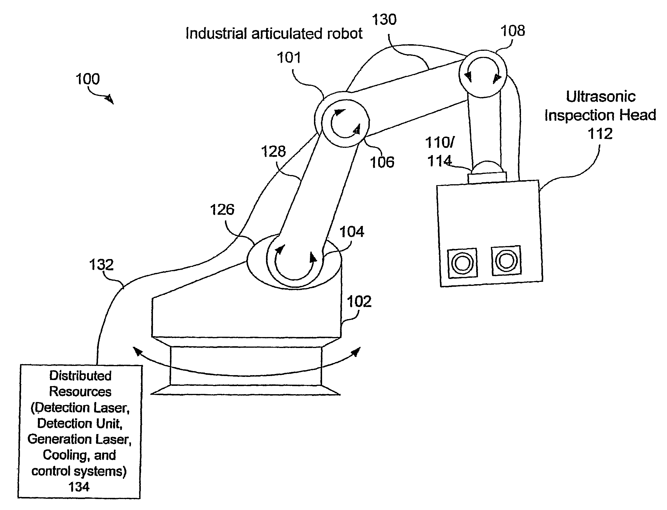
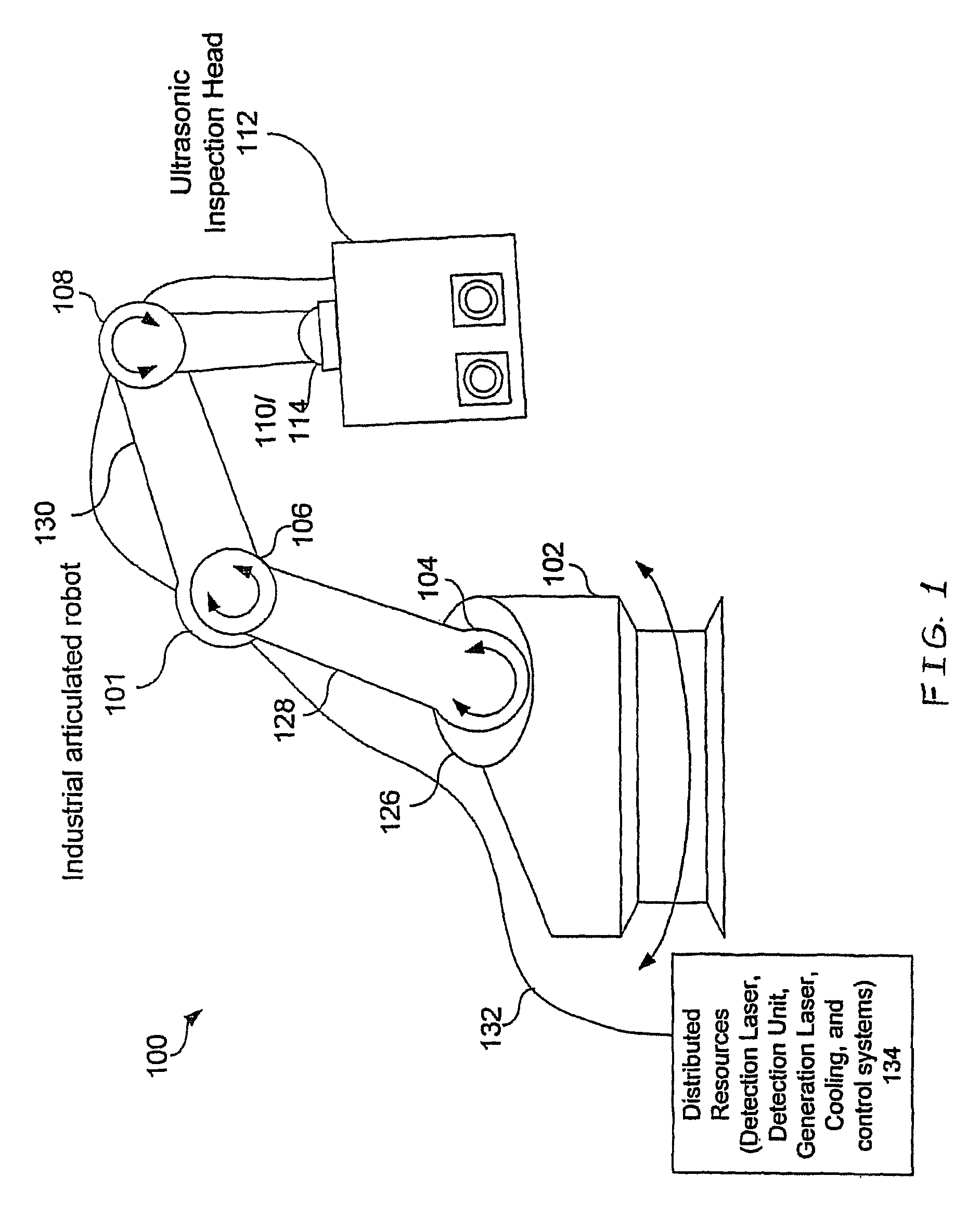
[0031]Laser-ultrasonic inspection has been demonstrated as a cost effective tool for the non-destructive evaluation (NDE) of polymer-matrix composites. As these composites are increasingly used in different industries, the quantity and complexity of composite parts are increasing. Also, the installed base of composites is increasing as well. As the size and complexity of objects fabricated from composites increase, it becomes more and more difficult to position the laser-ultrasonic sensors relative to the surface to be inspected. Embodiments of the invention disclosed here propose a solution to this problem.

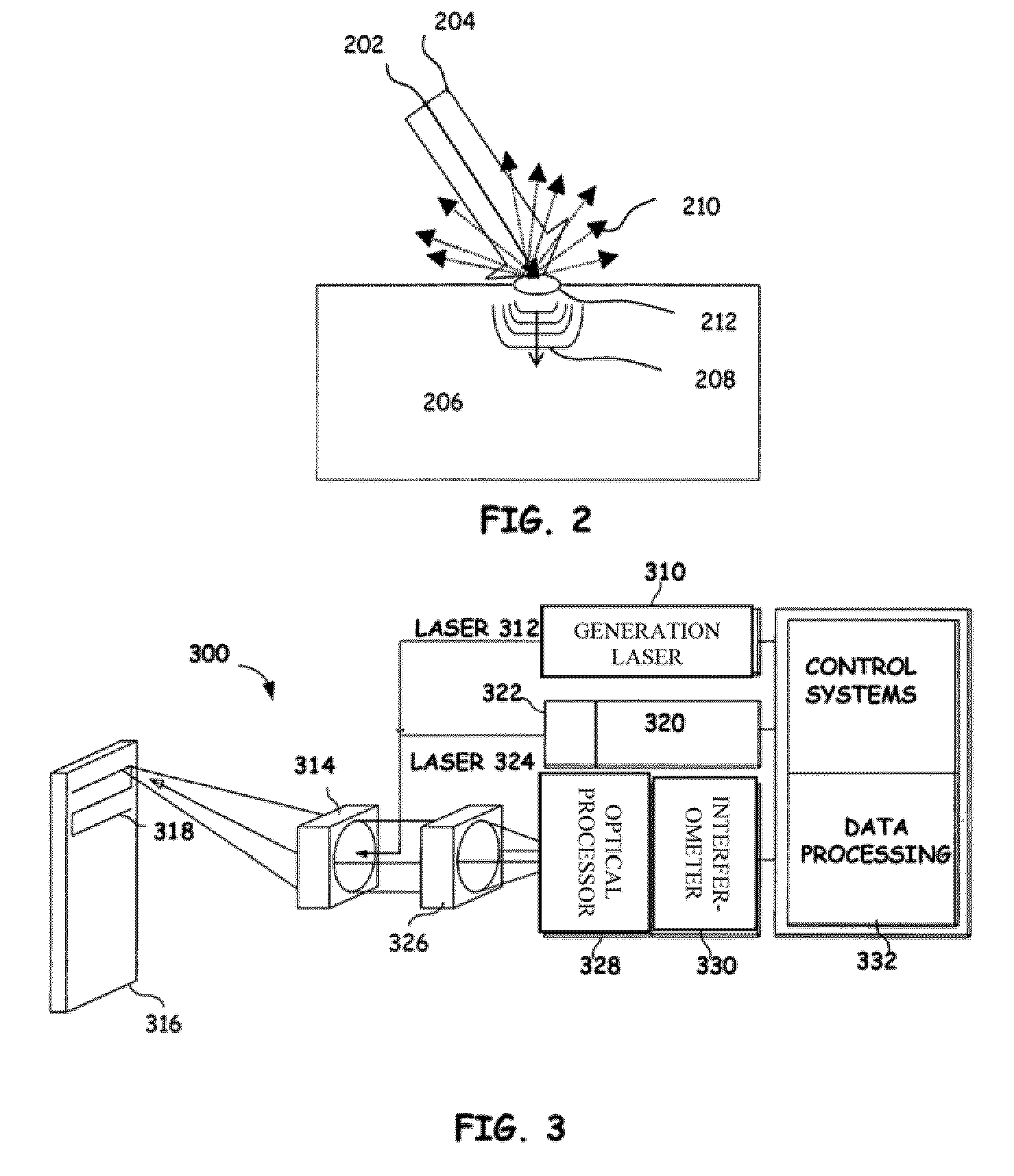
[0032]One embodiment places the laser-ultrasonic sensor at the end of an articulated robot (i.e. laser ultrasonic head). Laser-ultrasonic inspections are usually carried out by moving the laser ultrasonic se...


PUM

PropertyMeasurementUnit
wavelengthaaaaaaaaaa
poweraaaaaaaaaa
mean time between failureaaaaaaaaaa

Abstract

An ultrasonic non-destructive evaluation (NDE) system operable to inspect target materials is provided. This ultrasonic NDE system includes an articulated robot, an ultrasound inspection head, a processing module, and a control module. The ultrasound inspection head couples to or mounts on the articulated robot. The ultrasound inspection head is operable to deliver a generation laser beam, a detection laser beam, and collect phase modulated light scattered by the target materials. The processing module processes the phase modulated light and produces information about the internal structure of the target materials. The control module directs the articulated robot to position the ultrasound inspection head according to a pre-determined scan plan.

Description

RELATED APPLICATIONS[0001]This application claims priority to and incorporates by reference in its entirety for all purposes U.S. Provisional Application No. 60 / 871,680 filed on 22 Dec. 2006 entitled “ARTICULATED ROBOT FOR LASER ULTRASONIC INSPECTION” to Thomas E. Drake.[0002]This application incorporates by reference in its entirety for all purposes U.S. Pat. No. 6,633,384, filed Jun. 30, 1999 which claimed the benefit of U.S. Provisional Application No. 60 / 091,240 filed on 30 Jun. 1998 and which is assigned to the assignee of the present application.[0003]This application incorporates by reference in its entirety for all purposes U.S. Pat. No 6,122,060, filed Sep. 19, 2000 which claimed the benefit of U.S. Provisional Application No. 60 / 091,229 filed on 30 Jun. 1998 entitled “METHOD AND APPARATUS FOR DETECTING ULTRASONIC SURFACE DISPLACEMENTS USING POST-COLLECTION OPTICAL AMPLIFICATION” to Thomas E. Drake and which is assigned to the assignee of the present application.[0004]This ...

Claims


Application Information

Patent Timeline
Patent Type & Authority Patents(United States)
IPC IPC(8): G01N29/06G01N29/26
CPCG01N21/1702G10K15/046
Inventor DUBOIS, MARCDRAKE, JR., THOMAS E.YAWN, KENNETHOSTERKAMP, MARK
Owner LOCKHEED MARTIN CORP
Why Eureka
Try Eureka