Connecting system for tensile elements such as spokes

a technology of tensile elements and connecting systems, which is applied in the direction of manufacturing tools, couplings, transportation and packaging, etc., can solve the problems of increasing the weight of the wheel assembly, poor vibration-damping characteristics, and the steel spokes of the conventional bicycle wheel are quite heavy, so as to reduce the stress within the hub flange material, reduce the cost, and reduce the cost of components.

Active Publication Date: 2010-08-31
SCHLANGER RAPHAEL
View PDF6 Cites 24 Cited by
  • Summary
  • Abstract
  • Description
  • Claims
  • Application Information

AI Technical Summary

Benefits of technology

[0031]It is a further advantage of the present invention to provide a reduction in cost through the ability to utilize inexpensive and efficient manufacturing techniques and through the use of lower cost component parts. Since the spoke tension stresses of the present invention are distributed over a wider region of the hub flange interface, stresses are reduced within the hub flange material. Thus the strength requirements for the hub flange material are reduced and lower performance materials may be utilized, further reducing the cost as compared with conventional hubs. For example, the hub flange of some embodiments of the present invention may now be formed from relatively inexpensive polymer resins. These materials also lend themselves to lower-cost forming operations such as plastic injection molding.
[0032]The present invention is uniquely applicable to arrangements wherein the hub flange and / or rim are formed from polymeric materials. Many of these materials, especially engineering polymers, exhibit good strength characteristics and are relatively inexpensive and easy to mold. Heretofore, these materials have not been used successfully applied in hub flange and rim applications because they do not exhibit sufficient hardness to withstand the high contact stresses associated with conventional spoke attachment technology.
[0033]Further, fiber reinforced injection molding compounds may now be utilized in the present invention. With these high strength composite polymers, the injection molding process permits the fibers to attain a generally random orientation within the matrix. This is a significant benefit that would not apply if the hub were machined from a fiber reinforced plastic billet. Fiber reinforced billet is normally produced by an extrusion process where the fibers become highly aligned in the direction of extrusion. Thus, a hub shell machined from such a billet would have relatively low strength perpendicular to the direction of extrusion.
[0034]Some of the embodiments of the present invention also illustrate the ease with which duplex spokes may be incorporated into the present invention. These duplex spokes create the equivalent of two individual spokes using only a single series of manufacturing operations and are thus less expensive to produce.
[0035]The hub and hub flange of the present invention may be produced using ‘net shape’ molding techniques that reduce or eliminate the need for expensive machining operations. Since this design may be well suited to such molding or casting operations, the desired hub geometry may be produced with few, if any, secondary machining operations. In the case where subsequent machining is required, far fewer of these costly operations are anticipated than if the hub were produced from a billet or a forging. Further, in such a “net shape” forming operation, the amount of material waste is greatly reduced, particularly when compared to a part that is fully machined from billet.

Problems solved by technology

However, the steel spokes of conventional bicycle wheels are quite heavy and add significant weight to the wheel assembly.
In addition to their excessive weight, steel bicycle spokes have poor vibration-damping characteristics and tend to be very efficient at transmitting road vibration to the rider.
By transmitting vibration, rather than absorbing it, the conventional steel-spoke bicycle wheel lacks in rider comfort and control.
This causes the stress in the spoke to increase and makes the wheel more prone to spoke failure due to fatigue.
Spoke manufacturers have attempted to compensate for this shortcoming by thickening the wire in this region, but this solution results in considerable extra expense and weight.
This requires that the hub flange construction be based on expensive, higher strength materials and the use of more expensive forming processes, such as forging, rather than less costly processes, such as die casting or injection molding.
Further, these stresses require that the flange be designed with robust thickness, thus adding weight to the wheel assembly.
With a conventional hub flange, this creates a problem where the extra wide spoke cross section must pass through the round hole in the hub flange.
This additional operation adds considerable expense and weakens the hub flange as well.
This undesirable movement results in wear at the flange and additional flex at the rim and also causes the wheel to come out of alignment (true) rather easily.
However, when attempting to utilize them as spokes in bicycle wheel construction, these fibrous materials are far more difficult to efficiently couple or terminate than their steel-wire counterparts.

Method used


Image

  • Connecting system for tensile elements such as spokes
  • Connecting system for tensile elements such as spokes
  • Connecting system for tensile elements such as spokes

Examples


Embodiment Construction

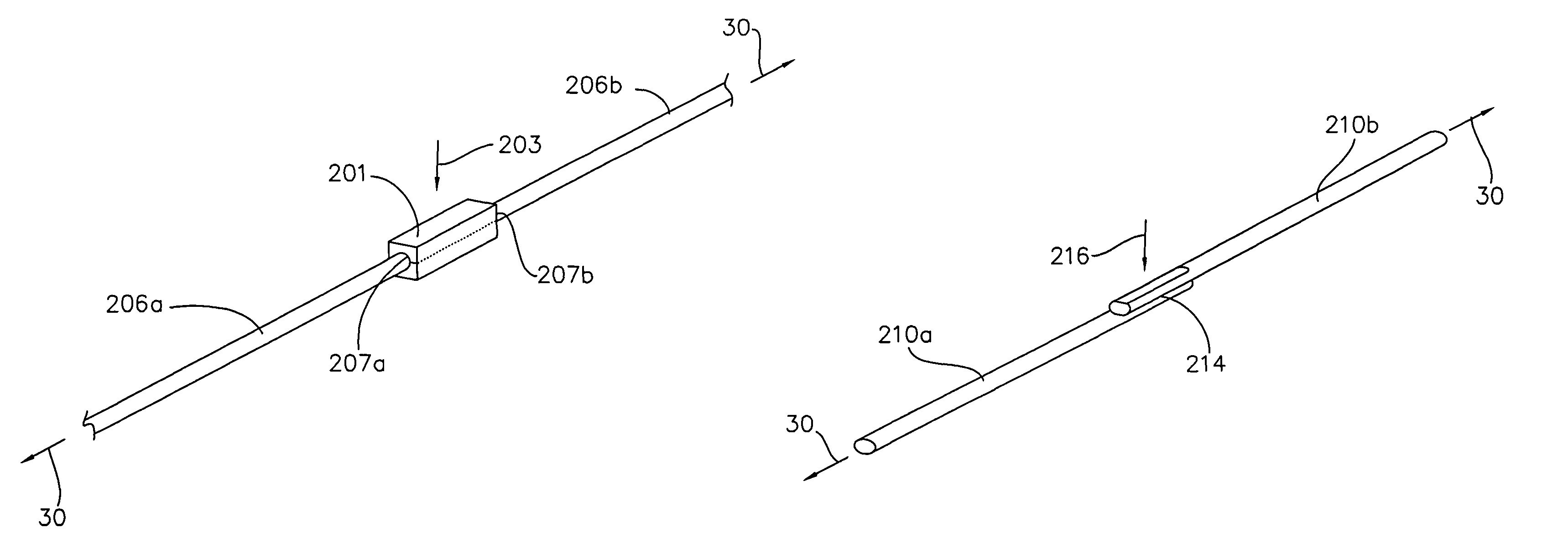
[0106]The present invention comprises a longitudinal tensile element having an end portion and a cross-section thereof, a bracing element, and a tensile axis of applied tensile load along the longitudinal tensile element. The longitudinal tensile element is connected to at least one bracing element via a welded connection between the longitudinal tensile element and either the bracing element or an intermediate element.

[0107]A longitudinal tensile element is a generally long slender element, with a length greater than its cross sectional width, and with a longitudinal axis extending generally along its length. The longitudinal tensile element includes sidewall surface(s) that extend generally along its length. As such, the longitudinal axis is generally parallel to the sidewall surface. Some examples of a longitudinal tensile element include the spoke of a vehicle wheel, a guy wire, a control cable, or a tendon. In most of the embodiments of the present invention, the longitudinal t...


PUM


Abstract

A tensile connector assembly comprising a longitudinal tensile element having a longitudinal axis, an end portion and a cross-section, a connecting element connected to the longitudinal tensile element, and a bracing element connected to the longitudinal tensile element. With a tensile axis of applied tensile load along said longitudinal tensile element. Where the longitudinal tensile element is anchored to the bracing element and the connecting element is connected to the longitudinal tensile element via a welded connection at a welded interface. Where the connections permit the longitudinal tensile element to support said tensile load along the tensile axis.

Description

CROSS-REFERENCE TO RELATED APPLICATION[0001]This application is a Continuation-In-Part of U.S. patent application Ser. No. 10 / 755,653, filed Jan. 12, 2004 now U.S. Pat. No. 7,357,460.BACKGROUND OF THE INVENTION[0002](1) Field of the Invention[0003]The present invention relates to an improved connection system for a tensile element, particularly applicable to the spoke of a vehicle wheel, such as a bicycle wheel.[0004](2) Description of the Related Art[0005]Heretofore, the vast majority of bicycle wheels have been constructed using steel wire spokes that are connected, at their inner end, to a central hub component and, at their outer end, to a metallic rim hoop. The spokes are generally of steel construction while the hub and rim may be of aluminum or steel construction. The spokes, hub and rim are each formed as separate components that are then joined together with mechanical connections. These steel wire spokes commonly have one headed end for connection with the bicycle hub, wit...

Claims


Application Information

Patent Timeline
Patent Type & Authority Patents(United States)
IPC IPC(8): B60B5/02
CPCB60B1/003B60B1/0246B60B1/041B60B1/042B60B21/062B60B21/064B60B21/025Y10T403/4966Y10T403/471Y10T403/477
Inventor SCHLANGER, RAPHAEL
Owner SCHLANGER RAPHAEL
Why Eureka
Try Eureka