Memory cell shift estimation method and apparatus

a memory cell and shift estimation technology, applied in the field of magnetic resonance memory, can solve the problems of increasing the complexity of electronic systems, increasing the requirement for additional memory in systems, and the inability of memory cells which are programmed as reference cells to store user data

Active Publication Date: 2010-08-31
MICRON TECH INC
View PDF3 Cites 20 Cited by
  • Summary
  • Abstract
  • Description
  • Claims
  • Application Information

AI Technical Summary

Problems solved by technology

As the performance and complexity of electronic systems increases, the requirement for additional memory in systems also increases.
However, an issue with utilizing this method of determining

Method used


Image

  • Memory cell shift estimation method and apparatus
  • Memory cell shift estimation method and apparatus
  • Memory cell shift estimation method and apparatus

Examples


Embodiment Construction

[0020]In the following detailed description of the present embodiments, reference is made to the accompanying drawings that form a part hereof, and in which is shown by way of illustration specific embodiments in which the embodiments may be practiced. These embodiments are described in sufficient detail to enable those skilled in the art to practice the invention, and it is to be understood that other embodiments may be utilized and that process, electrical or mechanical changes may be made without departing from the scope of the present disclosure. The following detailed description is, therefore, not to be taken in a limiting sense.

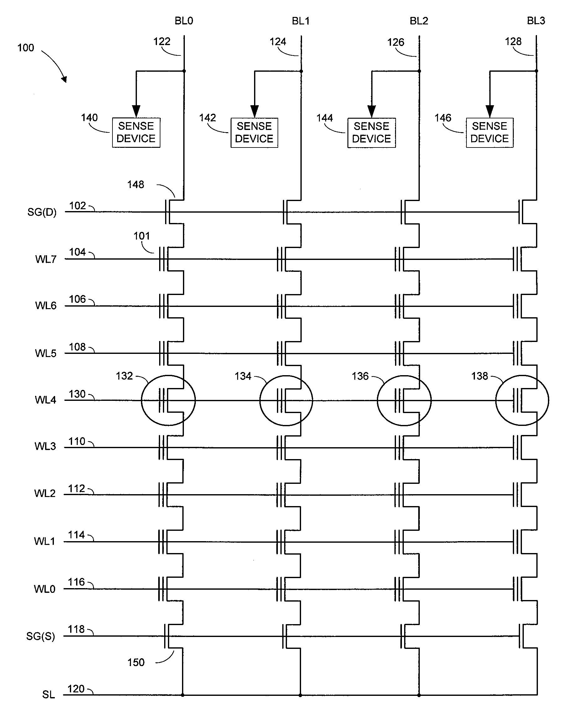
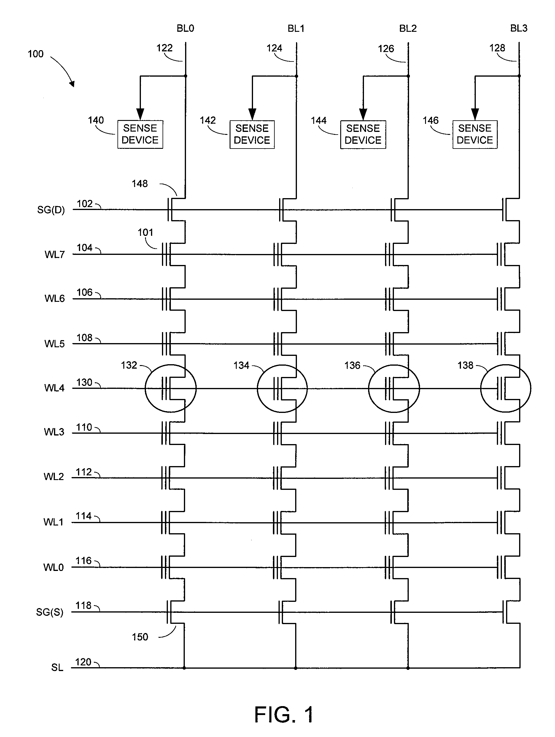
[0021]FIG. 3 illustrates a typical programming scheme for a number of reference cells in an array of memory cells 300. The memory array of FIG. 3 is similar to the memory array illustrated in FIG. 1. The source 120 and drain 102 lines and select gates 150 / 148 illustrated in FIG. 1 are not shown in FIG. 3 in order to improve the readability of the Figur...


PUM


Abstract

Memory devices and methods are disclosed, such as those facilitating interpolation methods for reference memory cells based on their reference state and/or location in an array of memory cells. For example, a group of reference cells programmed to a subset of possible data states are utilized to interpolate for data states other than those in the subset. Such embodiments might be used to reduce the quantity of reference cells required.

Description

TECHNICAL FIELD[0001]The present disclosure relates generally to semiconductor memory and more particularly, in one or more embodiments, to non-volatile memory devices.BACKGROUND[0002]Flash memory devices have developed into a popular source of non-volatile memory for a wide range of electronic applications. Flash memory devices typically use a one-transistor memory cell (e.g., floating gate) that allows for high memory densities, high reliability, and low power consumption. Changes in threshold voltage of the cells, through programming of charge storage or trapping layers or other physical phenomena, determine the data value of each cell. Common uses for flash memory and other non-volatile memory include personal computers, personal digital assistants (PDAs), digital cameras, digital media players, digital recorders, games, appliances, vehicles, wireless devices, mobile telephones, and removable memory modules, and the uses for non-volatile memory continue to expand.[0003]Flash mem...

Claims


Application Information

Patent Timeline
IPC IPC(8): G11C11/34
CPCG11C11/5642G11C16/28G11C16/3418G11C16/3422G11C7/14G11C2211/5634
Inventor SARIN, VISHAL
Owner MICRON TECH INC
Why Eureka
Try Eureka