Standing duster article

a duster and article technology, applied in the field of standing duster articles, can solve the problems of coarse strips of conventional dust mops, inconvenient cleaning of carpet cleaners, and inability to meet the effect of dust cloth and conventional dust mops that adopt a plurality of nonwoven fabric strips, and achieve excellent dusting effect, reduce dust raise, and more dust powder

Inactive Publication Date: 2010-09-07
YANG YA CHING
View PDF3 Cites 10 Cited by
  • Summary
  • Abstract
  • Description
  • Claims
  • Application Information

AI Technical Summary

Benefits of technology

[0016]An aspect of the present invention is to provide a standing duster article capable of reducing the raise of dust, wherein the fiber bundles are not likely to be tangled and the duster portion is gathered onward. The standing duster article comprises a plurality of nonwoven fabric layers and fibers undergoing hot-pressing and cutting to generate a slit in the middle, which are used in conjugation with a spiral handle. Since the nonwoven fabric layer is always shorter than the segmented intermingled yarn layer, an excellent dusting effect can be obtained by combining the nonwoven fabric layers with the segmented intermingled yarn layer that is always longer than the nonwoven fabric layers. Since the intermingled yarn of the segmented intermingled yarn layer used in the present invention comprises alternate loose and tight segments, the fibers on the loose segments of the intermingled yarn are capable of capturing more dust powder. The alternate loose and tight segments are formed by twisting the intermingled yarn, such that each of the bundles of the intermingled yarn is effectively bound and will not tangle with each other.
[0017]A further aspect of the present invention is to provide a standing duster article consisting of the dusting portion and the spiral handle in conjugation, such that only the dusting portion has to be replaced after getting dirty or damaged due to a long-term use, thereby decreasing the cost of replacement. As shown, the protruding portions of the spiral handle of this invention are intentionally narrowed, such that the whole handle can be freely used at any angle while cleaning.
[0018]A still further aspect of this invention is to provide a standing duster article with simple structure, which is easy-to-handle, durable, and environmental friendly etc.

Problems solved by technology

1. Since dust particles are tiny, the effect of the dust cloth and the dust mops that adopts a plurality of nonwoven fabric strips is not satisfying and it usually requires repetition of wiping to obtain better effect.
Moreover, the dust particles remaining on the dust cloth tend to scratch the articles to be cleaned.2. The strips of the conventional dust mops are coarse and the filaments of the conventional dust mops are too soft that they tend to get tangled.
As a result, the strips get dirty easily and the filaments get tangled easily too.
It is also difficult to reach and clean the inside.
Therefore, it is not environmental friendly nor cost-effective.3. The users have to directly touch the dust cloth while using it, dust and bacteria thus are prone to stick to the users' skin and further do harm to the users' health.4. The conventional dust cloth or dust mops are required to be used horizontally, which may suppresses the dust particles between the dust cloth or dust mops and the article to be cleaned and tends to scratch the articles to be cleaned.

Method used


Image

  • Standing duster article
  • Standing duster article
  • Standing duster article

Examples


Embodiment Construction

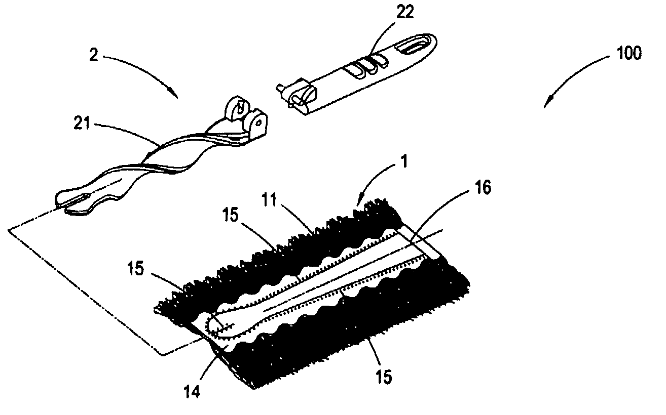
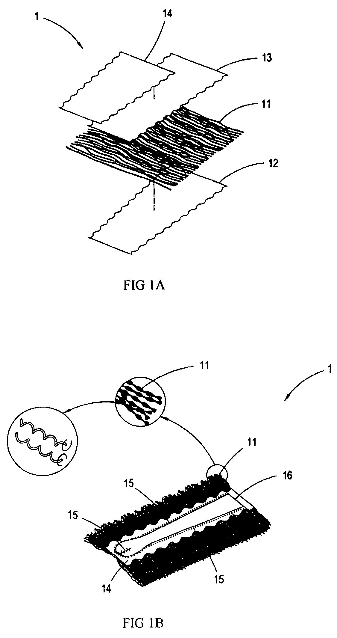
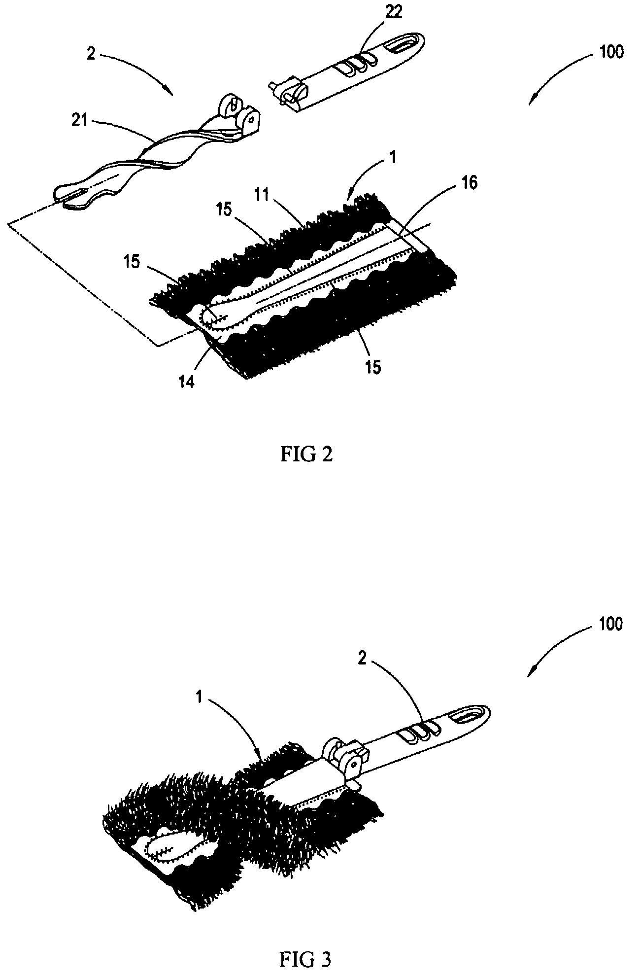
[0028]Please refer to FIGS. 1A to 3, wherein FIG. 1A is an exploded view of the dusting portion of the standing duster article according to the first embodiment of the present invention; FIG. 11B is an illustrative view together with an enlarged view of the dusting portion of the standing duster article according to the first embodiment of the present invention; FIG. 2 is an exploded view of the dusting portion and the spiral handle of the standing duster article according to the first embodiment of the present invention; and FIG. 3 is a schematic view of the dusting portion in conjugation with the spiral handle of the standing duster article according to the first embodiment of the present invention. According to the figures, it can be know that the duster article of the present invention consists of a dusting portion 1 and a spiral handle 2, wherein the dusting portion 1 comprises: a hot-meltable nonwoven fabric layer 12; a segmented intermingled yarn layer 11 disposed on the hot-...


PUM

PropertyMeasurementUnit
lengthaaaaaaaaaa
twisting forcesaaaaaaaaaa
widthaaaaaaaaaa

Abstract

A standing duster article consisting of a dusting portion and a spiral handle, wherein the dusting portion is comprised of a segmented intermingled yarn layer, a hot-meltable nonwoven fabric layer, a smooth nonwoven fabric layer, and a nonwoven / woven fabric layer; the segmented intermingled yarn layer is interleaved between the hot-meltable nonwoven fabric layer and the smooth nonwoven fabric layer; the nonwoven / woven fabric layer is further superimposed on the smooth nonwoven fabric layer; a hot-pressing process is carried out to fuse the segmented intermingled yarn layer, the hot-meltable nonwoven fabric layer, the smooth nonwoven fabric layer, and the nonwoven / woven fabric layer; the resulted lamination after fusion is cut by a cutting apparatus, so as to generate a slit in the middle to form the dusting portion which is easy to be folded to form two elongated openings; and a spiral end of the spiral handle is inserted into the openings to form the duster article with the spiral dusting portion. Since the intermingled yarn of the segmented intermingled yarn layer used in the present invention comprises alternate loose and tight segments, the fibers on the loose segments of the intermingled yarn are capable of capturing more dust powder. The alternate loose and tight segments are formed by twisting the intermingled yarn, such that each of the bundles of the intermingled yarn is effectively bound and will not tangle with each other. Further, it is easy to install or remove the spiral handle in or from the dusting portion by such design.

Description

BACKGROUND[0001]1. Technical Field[0002]The present invention relates to a standing duster article, in particular a duster article structure comprising a plurality of nonwoven fabric layers and fibers, wherein the nonwoven fabric layers undergo hot-pressing and cutting, so as to generate a slit in the middle to receive the spiral handle, thereby forming a dusting surface with multi-layers and better dusting effect.[0003]2. Prior Art[0004]There are various dusting tools on the market, from simple dust cloth to all kinds of dust mops. These dusting tools posses dusting function, however, the effect is not remarkable and thus results in the following shortcomings:[0005]1. Since dust particles are tiny, the effect of the dust cloth and the dust mops is not satisfying and it usually requires repetition of wiping to obtain better effect. Moreover, the dust particles remaining on the dust cloth tend to scratch the articles to be cleaned.[0006]2. The front end of the conventional dust mops ...

Claims


Application Information

Patent Timeline
Patent Type & Authority Patents(United States)
IPC IPC(8): A47L13/10
CPCA46B3/06A46B5/06A46B7/04A47L13/38A47L13/46A46B2200/3026
Inventor YANG, YA CHINGPAN, YI-JUN
Owner YANG YA CHING
Why Eureka
Try Eureka