Direct sludge drying and incineration system and method

A sludge drying and direct technology, applied in combustion methods, chemical instruments and methods, indirect carbon dioxide emission reduction, etc., can solve the problems of heat loss, limited technical effect, ash clogging, etc., to maintain self-heat balance and system operation. Smooth and prevent coking problems

Active Publication Date: 2020-09-18
SHANDONG LONGZHIYUAN ENERGY SAVING ENVIRONMENTAL PROTECTION TECH CO LTD
View PDF13 Cites 0 Cited by
  • Summary
  • Abstract
  • Description
  • Claims
  • Application Information

AI Technical Summary

Problems solved by technology

However, the existing direct sludge drying and incineration system still has some shortcomings in actual use. First, due to the high water content of the sludge, the water content of the dried sludge is still between 30% and 40%. Therefore, the sludge cannot be fully incinerated by itself. The existing technology is to solve the problem by continuously adding auxiliary fuel (generally using biomass or natural gas as auxiliary fuel) to the incinerator. The existing solutions have high cost and energy High energy consumption and potential safety hazards; Second, the problem of secondary combustion and coking of ash and slag often occurs in high-temperature dust collectors during sludge treatment, which seriously affects production efficiency. The main reason is that the sludge in the incinerator is fine powder and unburned And / or incompletely burned sludge fine powder is easy to float up through the outlet flue of the incinerator and enter the high-temperature dust collector, where it is secondary burned in the high-temperature dust collector, which in turn causes secondary combustion and coking of the ash in the lower ash section of the high-temperature dust collector. Finally, the feeding leg is blocked. The existing technology mainly solves it by using air supply, that is, blowing air to the middle of the incinerator to supplement oxygen, hoping to fully burn the sludge, but because the sludge is in the form of fine powder, the rising speed is very fast , so the existing air distribution method can only be effective for the edge of the sludge, and it is beyond the reach of the central area of ​​the sludge. There will still be a large amount of sludge that is not fully burned and enters the high-temperature dust collector for secondary combustion. The existing technical means The technical effect is limited, and the problem of coking of the high-temperature dust collector has not been completely solved; there is another way to achieve it by raising the height of the incinerator. Although this solution can also solve the problem, it has the problems of difficult construction and significantly increased costs, and the incinerator After heightening, there will be a problem of increased heat loss, which is not worth the loss compared with the problem of coking, so this scheme has basically been eliminated
The above two technical problems are the main factors restricting the development of the direct sludge drying and incineration system at present

Method used


Image

  • Direct sludge drying and incineration system and method
  • Direct sludge drying and incineration system and method
  • Direct sludge drying and incineration system and method

Examples


Embodiment 1

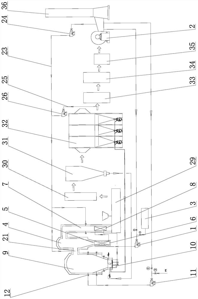
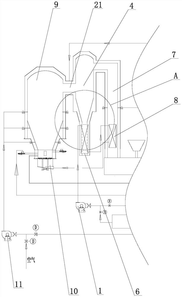
[0042] Such as Figure 1-7 As shown, a direct sludge drying and incineration system includes:

[0043] a power unit for feeding gas into a preheating unit which heats said gas;

[0044] The preheating unit includes an air preheater A6 arranged in the high temperature dust collector 4 and an air preheater B8 arranged in the inlet flue 7 of the dryer, one end of the air preheater A6 communicates with the power unit, The other end communicates with the air preheater B8, the air preheater B8 communicates with the air chamber 10 of the incinerator 9, and the air preheater A6 is arranged in the lower ash section 5 of the high temperature dust collector. By designing primary fan 1, air preheater A6 and air preheater B8, the air preheater here can be purchased directly, mainly to achieve the purpose of heat exchange. Generally, the gas can reach 100 after heat exchange by air preheater A ℃-150℃, while the ash temperature in the lower ash section of the high-temperature dust collecto...

Embodiment 2

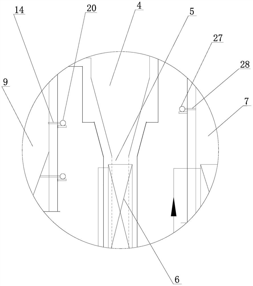
[0060] Such as Figure 6-7 As shown, the vertical injection angle 19 between the first direction 16 and the second direction 17 is greater than 0 and less than 90°, and the horizontal injection angle 18 between the first direction 16 and the second direction 17 is greater than 0 and less than 90°. This solution is more conducive to slowing down the rising speed of the fine sludge powder, and further facilitates the full combustion of the fine sludge powder in the incinerator 9 .


PUM


Abstract

The invention relates to a direct sludge drying and incineration system and method. The direct sludge drying and incineration system comprises a power unit and a preheating unit, wherein the power unit is used for sending gas into the preheating unit, and the preheating unit heats the gas; and the preheating unit comprises an air preheater A arranged in a high-temperature dust collector and an airpreheater B arranged in an inlet flue of a dryer, one end of the air preheater A communicates with the power unit, the other end of the air preheater A communicates with the air preheater B, the airpreheater B communicates with an air chamber of an incinerator, and the air preheater A is arranged at an ash-falling section of the high-temperature dust collector. The direct sludge drying and incineration system and method have the advantages that the process design is more reasonable, energy consumption is reduced, energy saving and emission reduction are realized, coking is avoided, and the system operates more smoothly.

Description

Technical field: [0001] The invention relates to the technical field of sludge treatment, in particular to a direct sludge drying and incineration system and a drying and incineration method thereof. Background technique: [0002] Sludge is a solid sediment produced in the process of sewage treatment. It mainly contains a large amount of organic debris, bacteria, inorganic particles and colloids. If it is discharged randomly, it will pollute the environment. The sludge treatment method with dry incineration as the core is currently a relatively reasonable and effective treatment method. The use of dry incineration treatment method is more conducive to carbonization of organic matter, killing pathogens, reducing sludge volume, and is conducive to reducing sludge treatment. Quantification, harmlessness, stabilization and resource utilization. This method has been promoted step by step. [0003] At present, according to whether the high-temperature flue gas produced by sludge...

Claims


Application Information

Patent Timeline
Patent Type & Authority Applications(China)
IPC IPC(8): F23G7/00F23G5/04F23G5/46F23L9/00F23L15/04F23J15/02F23J15/06C02F11/13
CPCC02F2303/10C02F11/13F23G5/04F23G5/46F23G7/001F23G2206/10F23G2209/12F23J15/02F23J15/022F23J15/06F23L9/00F23L15/04Y02E20/34
Inventor 赵夫才赵丽萍尤洪北尤作超
Owner SHANDONG LONGZHIYUAN ENERGY SAVING ENVIRONMENTAL PROTECTION TECH CO LTD
Why Eureka
Try Eureka