
Shielded parallel cable

a parallel cable and shielding technology, applied in the direction of cables, insulated conductors, conductors, etc., can solve the problems of signal loss, many discontinuities of shielding helically applied, and the price of fiber optic cables and transceivers has not dropped to a level, so as to achieve low insertion loss performance

Active Publication Date: 2010-09-07
AMPHENOL CORP
View PDF20 Cites 83 Cited by
  • Summary
  • Abstract
  • Description
  • Claims
  • Application Information

AI Technical Summary

Benefits of technology

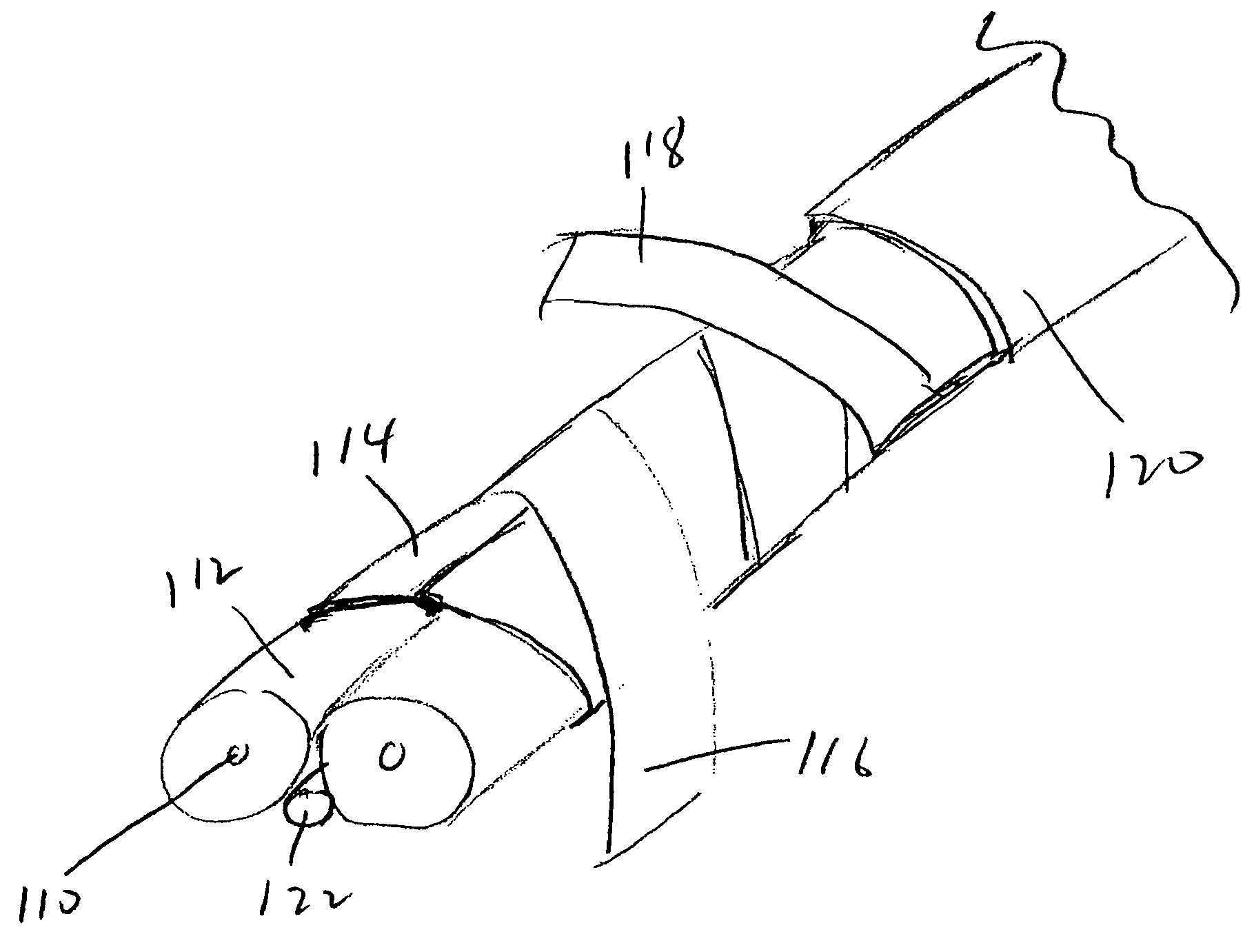
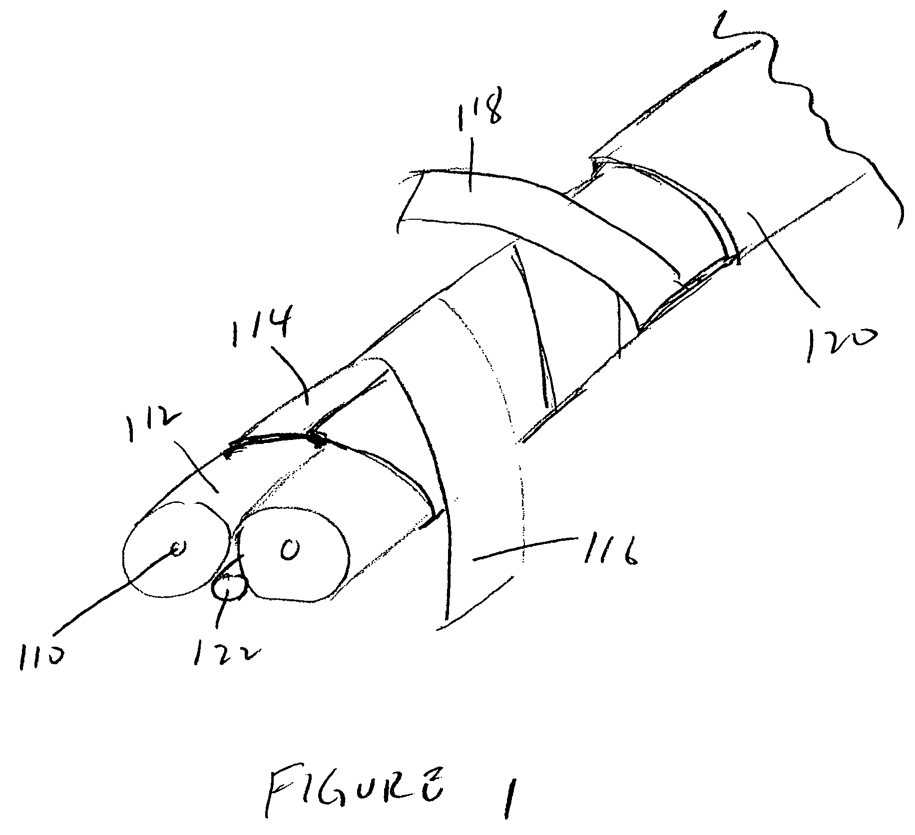
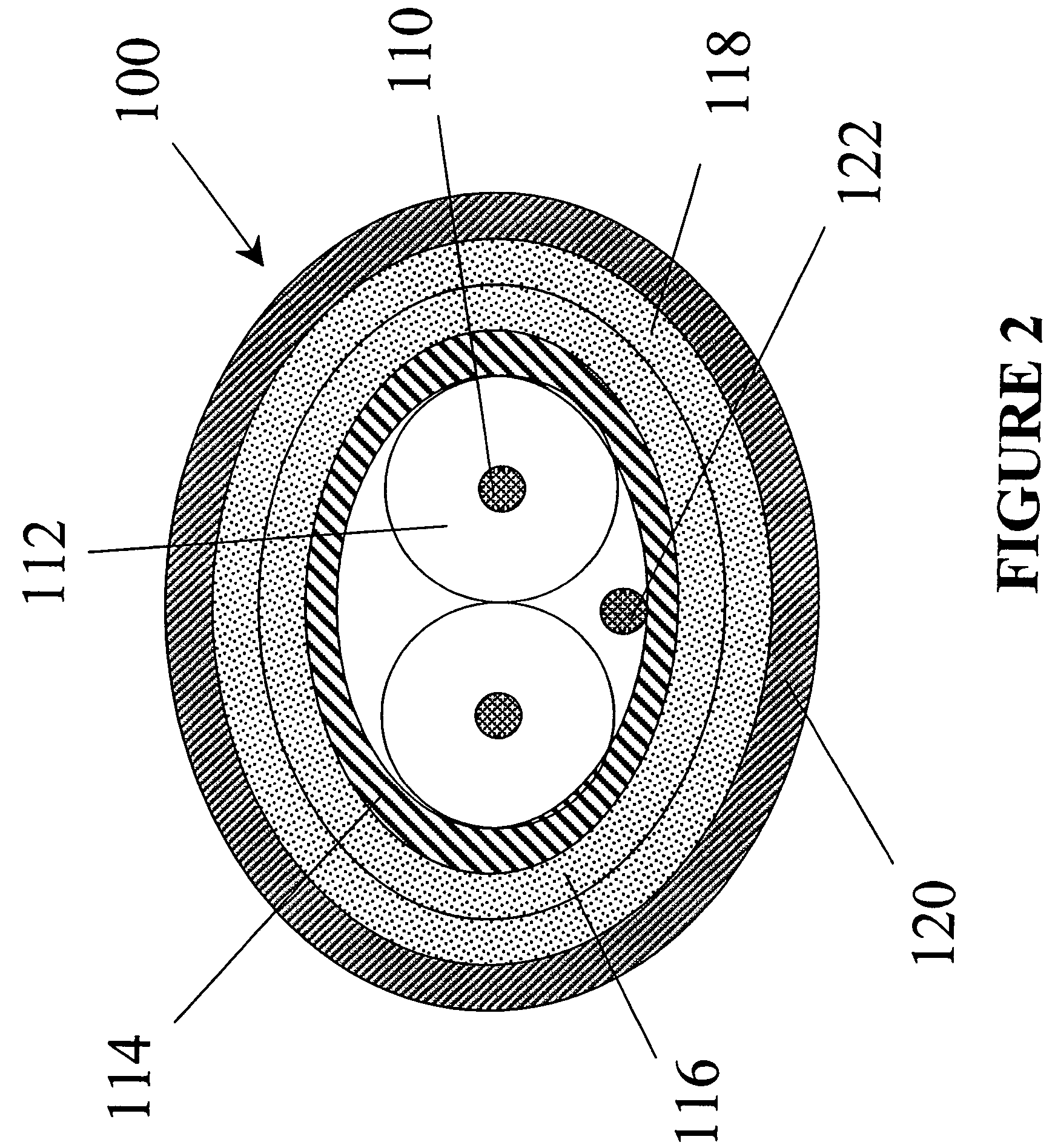
The present invention provides an improved shielded parallel pair cable for transmitting electrical signals with low insertion loss performance. The cable has at least one pair of insulated conductors and an optional drain wire, which are longitudinally covered by a shielding tape. The shielding tape is then covered with two layers of polymeric tape spirally wrapped around the shielding tape in opposite helical directions. The cable is made by wrapping a shielding tape around a core and then adding two layers of polymeric tape in opposite directions. The shielding tape is preferably made of a metallic sheet with adhesive applied in a checker-board pattern.

Problems solved by technology

However, despite the increased availability of fiber optic cables, the price of fiber optic cables and transceivers have not dropped to a level where it is always practicable to use.
However, a helically applied shield has many discontinuities.
These repeated interruptions cause signal loss, measured as increased attenuation.

Method used


Image

  • Shielded parallel cable
  • Shielded parallel cable
  • Shielded parallel cable

Examples


examples

[0034]The following Examples compare cables of the present invention with other cables. FIG. 5 compares a cable with a longitudinally wrapped shielding tape in accordance with the invention with a comparable cable with spiral wrapped shielding tape. The results clearly show improved attenuation with the longitudinally wrapped shielding tape. Specifically, the longitudinally wrapped cable can be about 13% longer for equal attenuation.

[0035]FIG. 6 compares three cables for differential mode to common mode conversion. One of the cables contains a single polymeric tape helically wrapped around the shielding tape. Two of the cables contain two polymeric tapes helically wrapped in opposing directions around the shielding tape in accordance with the invention. All three cables contain longitudinally wrapped shielding tapes. The results clearly show that the opposing direction, double wrapped cables have substantially lower skew required to achieve the lowest mode conversion when compared t...


PUM

PropertyMeasurementUnit
thicknessaaaaaaaaaa
thicknessaaaaaaaaaa
electricalaaaaaaaaaa

Abstract

The cable of the present invention contains at least one pair of insulated conductors and an optional drain wire. The insulate conductors and drain wire is longitudinally covered in a shielding tape, which preferably comprises a metallic sheet having an adhesive applied on selected portions of a surface of the metallic sheet. The adhesive is preferably applied in a checker board pattern so that the surface having adhesive thereon contains areas of uncoated, exposed metal forming contact pads. The shielding tape is then covered with two layers of polymeric tapes in opposite helical directions. The polymeric tape is preferably constructed of a polymeric sheet having a layer of adhesive disposed on a surface thereof. In a preferred embodiment, the tapes are wrapped around the shielding tape in opposite directions such that the adhesive surfaces face each other. The tapes are then optionally covered with a jacket.

Description

FIELD OF THE INVENTION[0001]The present invention relates to shielded electric cables for the transmission of electrical signals through the cables. In particular, the present invention provides improved shielded parallel pair cables for achieving low insertion loss performance and method of making the cables.BACKGROUND OF THE INVENTION[0002]Electrical cables for data transmission are well known. One common cable is a coaxial cable. Coaxial cables generally comprise an electrically conductive wire surrounded by an insulator. The wire and insulator are surrounded by a shield, and the wire, insulator and shield are surrounded by a jacket. Coaxial cables are widely used and best known for cable television signal transmission and ethernet standard communications in local area networks. Coaxial cables can transmit at much higher frequencies than a standard twisted pair wire and, therefore, have a much greater transmission capacity. In addition, coaxial cables have very little crosstalk, ...

Claims


Application Information

Patent Timeline
Patent Type & Authority Patents(United States)
IPC IPC(8): H01B11/00H01B11/02
CPCH01B11/1008H01B11/1091
Inventor VAUPOTIC, GREGORYTASSMER, TIMOTHYBOOTH, CARL
Owner AMPHENOL CORP
Learn More