Optimized electric machine for smart actuators

an electric machine and actuator technology, applied in the direction of windings, magnetic circuit rotating parts, magnetic circuit shapes/forms/construction, etc., can solve the problems of not being able to exhibit all of the desired operating characteristics, sacrifice other operating characteristics, and doing so at the expense, so as to achieve high torque to ampere ratio, high torque to inertia ratio, and optimal operating characteristics

Inactive Publication Date: 2010-09-07
GM GLOBAL TECH OPERATIONS LLC
View PDF11 Cites 38 Cited by
  • Summary
  • Abstract
  • Description
  • Claims
  • Application Information

AI Technical Summary

Benefits of technology

[0003]An advantage of an embodiment of the invention is an electric machine that provides optimal operating characteristics such as a high torque to ampere ratio, a high torque to inertia ratio, and low torque ripple.
[0004]An embodiment contemplates an electric machine. The electric machine includes a plurality of magnets for generating a first magnetic field. A magnet holder retains the plurality of magnets. The magnet holder has a circular configuration with the plurality of magnets being evenly positioned around the circular configuration of the magnet holder. A first stator is disposed radially outward from the magnet for generating a second magnetic field. The magnet and the first stator have a first air gap formed therebetween. The first stator includes a plurality of stator poles separated by slots with each of the stator poles having a concentrated winding with a respective number of turns formed around each respective stator pole. Each respective concentrated winding within the first stator comprises non-overlapping windings. A second stator is disposed radially inward from the magnet for generating a third magnetic field. The magnet and the second stator have a second air gap formed between. The second stator has a plurality of stator poles separated by slots with each of the stator poles having a concentrated winding with a respective number of turns formed around each respective stator pole. Each respective concentrated winding within the second stator comprises non-overlapping windings. The magnet holder and magnets retained therein are rotatable between the first stator and second stator. The employment of concentrated windings of the first stator and the second stator increases the active length of the stator within a package size by reducing the end turn length, and as a result, increases the torque density. The concentrated winding reduces an overhang of each respective winding with respect to each stator pole of each stator for improving machine efficiency.

Problems solved by technology

However, achieving a respective specific operating characteristic typically results in the sacrifice of other operating characteristics.
While each of the above examples achieve one of the desired operating characteristics, this is often done at the expense of not obtaining one of the other respective desired operating characteristics.
That is, none of the devices described above are capable of exhibiting all of the desired operating characteristics in a single electric machine.

Method used


Image

  • Optimized electric machine for smart actuators
  • Optimized electric machine for smart actuators
  • Optimized electric machine for smart actuators

Examples


Embodiment Construction

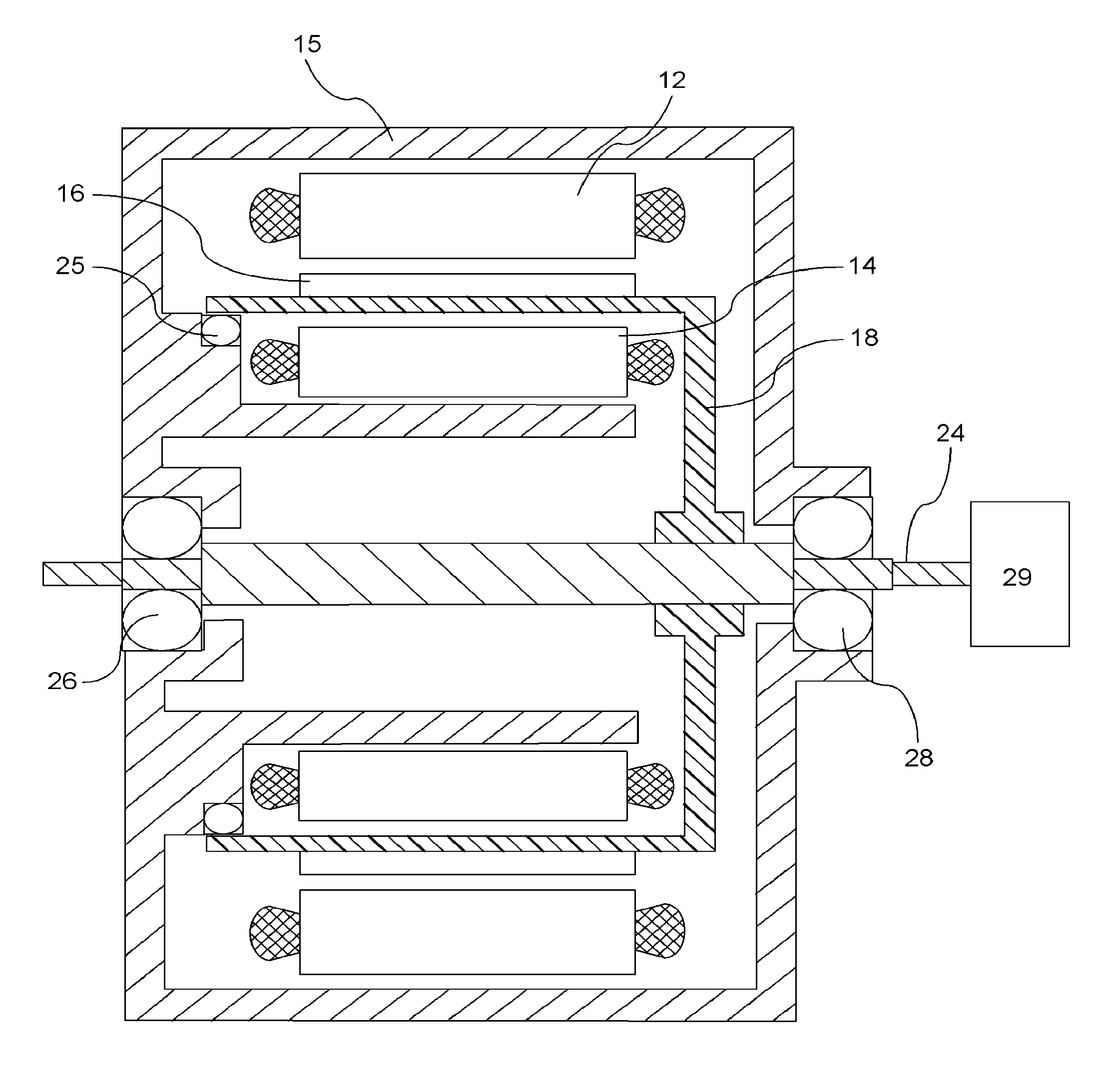
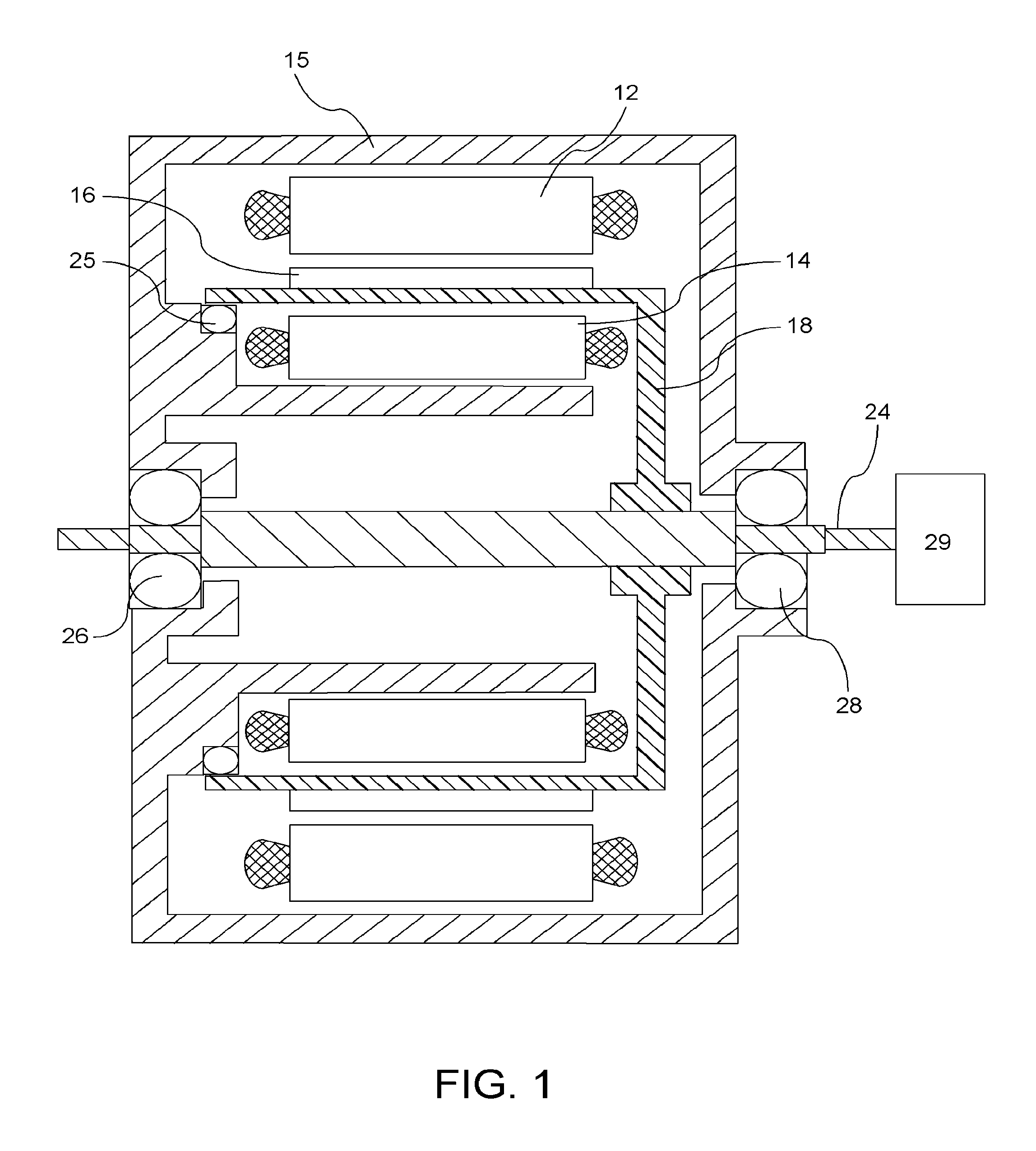
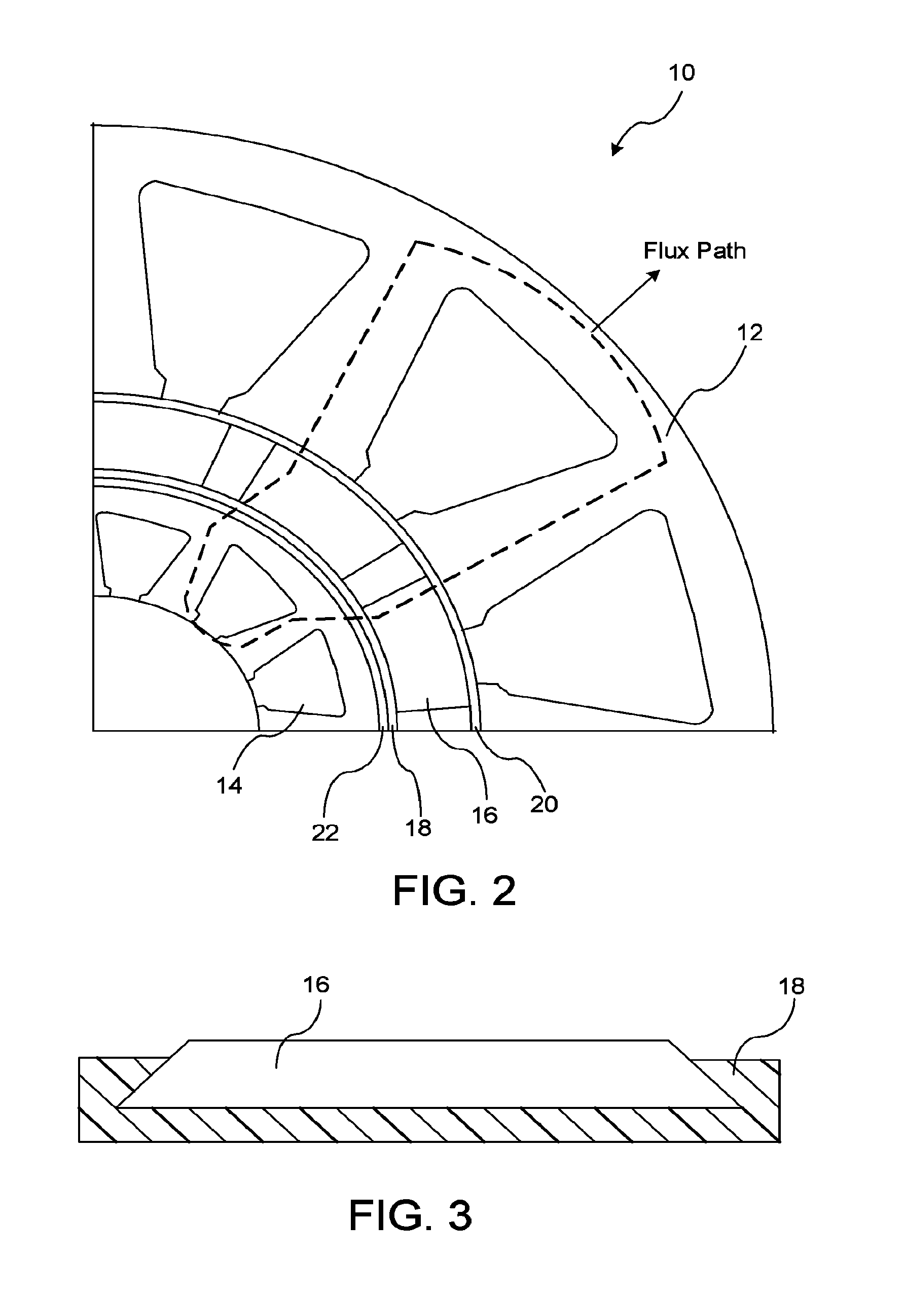
[0014]Referring to both FIGS. 1 and 2 there is shown a cross-section section views of an electric machine 10 along a diametric plane and a transverse plane, respectively. The electric machine 10 as described herein is used for devices and systems that require high torque and fast response times such as semi-active or active suspension systems, electric power steering systems, electromechanical braking systems or like systems. The electric machine 10 is a dual stator electric machine having a first stator 12 and a second stator 14 fixed within in a machine housing 15. The first stator 12 and the second stator 14 are coaxial to one another within the machine housing 15, and have different diameters. The first stator 12 and the second stator 14 have concentrated windings. Concentrated windings are non-overlapping windings which will be described in detail later.

[0015]A plurality of magnets 16 are radially disposed between the first stator 12 and second stator 14. The plurality of magne...


PUM


Abstract

An electric machine includes a plurality of magnets for generating a first magnetic field. A magnet holder retains the plurality of magnets. A first stator is disposed radially outward from the magnet holder for generating a second magnetic field. The first stator includes a plurality of stator poles separated by slots with each of the stator poles having a concentrated winding with a respective number of turns formed around each respective stator pole. A second stator is disposed radially inward from the magnet for generating a third magnetic field. The second stator has a plurality of stator poles separated by slots with each of the stator poles having a concentrated winding with a respective number of turns formed around each respective stator pole. The magnet holder and magnets retained therein are rotatable between the first stator and second stator.

Description

BACKGROUND OF INVENTION[0001]An embodiment relates generally to dual stator electric machines.[0002]Electric machines are typically designed to achieve a specific operating characteristic. For example, electric machines with drag cup rotors have very low inertia properties. Induction machines typically exhibit torque ripple free properties, whereas conventional permanent magnet synchronous machines exhibit high torque to ampere ratios. However, achieving a respective specific operating characteristic typically results in the sacrifice of other operating characteristics. While each of the above examples achieve one of the desired operating characteristics, this is often done at the expense of not obtaining one of the other respective desired operating characteristics. That is, none of the devices described above are capable of exhibiting all of the desired operating characteristics in a single electric machine.SUMMARY OF INVENTION[0003]An advantage of an embodiment of the invention i...

Claims


Application Information

Patent Timeline
Patent Type & Authority Patents(United States)
IPC IPC(8): H02K1/22
CPCH02K16/04H02K21/12H02K3/28
Inventor HAO, LEINAMUDURI, CHANDRA S.MURTY, BALARAMA V.
Owner GM GLOBAL TECH OPERATIONS LLC
Why Eureka
Try Eureka