
Method and apparatus for radar signal processing

a radar signal and processing method technology, applied in the field of radar technology, can solve the problems of increasing the hardware consumption of pulsed radar systems, requiring relatively little processing power for pulsed radar systems, and the cost of hardware remains relatively steady

Active Publication Date: 2010-09-07
VEONEER US LLC
View PDF27 Cites 56 Cited by
  • Summary
  • Abstract
  • Description
  • Claims
  • Application Information

AI Technical Summary

Benefits of technology

"The invention is a radar method and computer program product that uses multiple RF signals to determine the range and velocity of objects. The signals are transmitted sequentially and received after reflection from an object. The method involves determining the phase difference between the transmitted and reflected signals, organizing the samples in two dimensions, and processing the samples to determine the phase rotation frequency and range frequency of the object. The computer program product includes computer code to control the radar system and process the received data. The technical effect of the invention is to provide a more accurate and reliable method for radar detection and analysis."

Problems solved by technology

Initially, pulsed radar systems were favored for consumer and other low-cost radar applications because pulsed radar systems were hardware intensive, as opposed to processing intensive.
In other words, a pulsed radar system requires relatively little processing power because most of the work is performed by hardware, e.g., switches, oscillators, delay lines, and mixers.
The cost of hardware remains relatively steady, while the cost of digital signal processing decreases at a rapid pace.
The phase difference between the transmitted signal and the reflected signal for any one frequency does not provide enough information to determine the range to an obstacle.
Particularly, the difference in phase between the transmitted signal and the received signal does not disclose how many wavelength cycles exist in the round-trip delay between transmitted signal and received reflection signal.
With only two transmit frequencies, FSK modulation techniques cannot provide range measurement data unless there are at least two objects within the field of view of the radar that are moving at different velocities relative to the radar.
However, by increasing the number of frequencies transmitted, one can increase the number of obstacles that can be resolved.
In a real-world situation in which the obstacles may be moving or stationary, another layer of complexity in the signal processing is introduced.
Accordingly, even more complex modulation techniques and signal processing is necessary to provide sufficient information to distinguish the portion of the phase difference data that is the result of the Doppler Effect from the portion of the phase difference data that is the result purely of the range to the detected obstacle.
It is difficult to process such phase information in the time domain.

Method used


Image

  • Method and apparatus for radar signal processing
  • Method and apparatus for radar signal processing
  • Method and apparatus for radar signal processing

Examples


Embodiment Construction

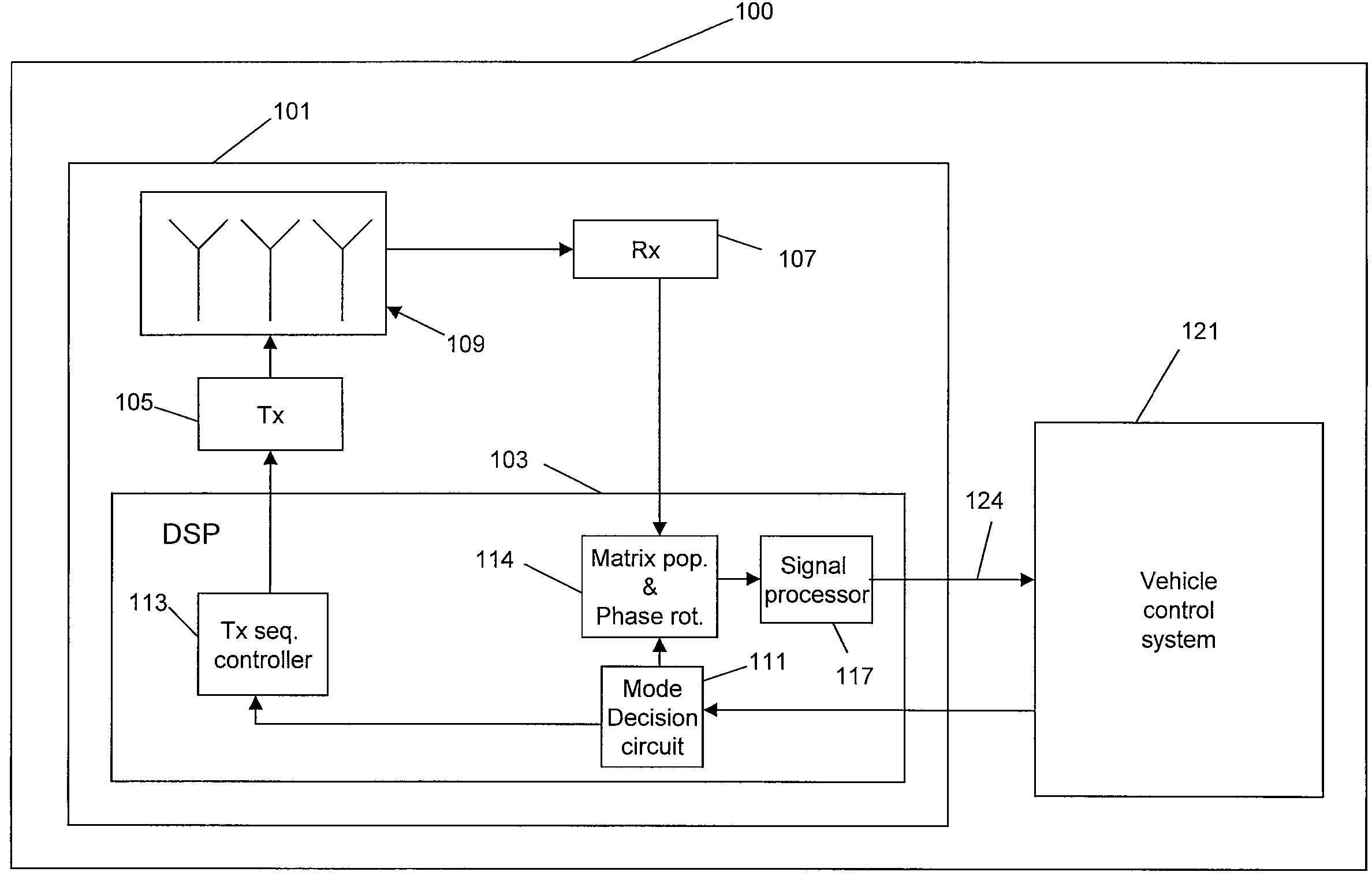
[0033]For sake of clarity, let us review some of the terminology utilized hereinabove. A “sample” is a single instance of the radar system transmitting a transmit signal of a given frequency and receiving the reflected return signal. A stepped frequency sweep is a plurality of samples taken at a plurality of different transmit signal frequencies over a defined frequency range in defined frequency steps. An up-chirped sequence is a plurality of stepped frequency sweeps in which each stepped frequency sweep has a higher frequency range than the preceding stepped frequency sweep. A down-chirped sequence is a plurality of stepped frequency sweeps in which each stepped frequency sweep has a lower frequency range than the preceding stepped frequency sweep. The information contained in a sample is the phase difference between the transmitted signal and the corresponding received signal. A “complete measurement set” refers to the plurality of samples that are processed collectively to provi...


PUM


Abstract

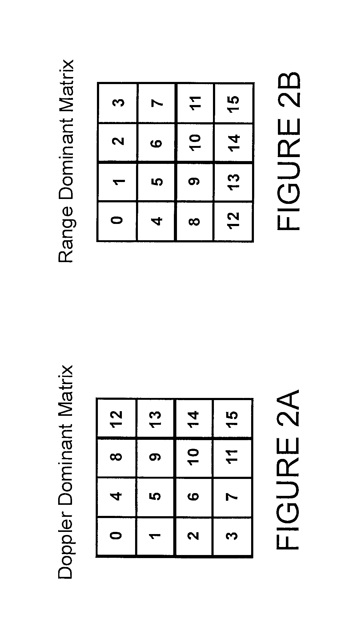
A radar apparatus and method for determining the range to and velocity of at least one object comprising, transmitting a plurality of RF signals, each comprising a particular frequency and being transmitted during a particular unique finite period, the plurality of signals collectively comprising at least one first subset of signals having the same frequency and at least one second subset of signals having different frequencies, receiving the plurality of signals after reflection from an object, determining a phase difference between each of the signals and the corresponding reflected signal, each piece of phase difference information herein termed a sample, organizing the samples in two-dimensions wherein, in a first dimension, all samples have the same frequency and, in a second dimension, all consecutive samples are separated from each other by a fixed time interval; processing the samples in the first dimension to determine a phase rotation frequency corresponding to the samples in the first dimension, the phase rotation frequency comprising a Doppler frequency for the at least one object, processing the samples in the second dimension to determine a second phase rotation frequency corresponding to the samples in the second dimension; the phase rotation frequency comprising Doppler frequency and range frequency for the at least one object; comparing the first phase rotation frequency to the second phase rotation frequency to distinguish range frequency from Doppler frequency of the at least one object; and converting the Doppler frequency to a velocity of the object and converting the range frequency to a range of the object.

Description

FIELD THE INVENTION[0001]The invention pertains to radar technology. More particularly, the invention pertains to methods and apparatus for processing continuous wave radar signals to maximize performance and / or increase flexibility of a radar system.BACKGROUND OF THE INVENTION[0002]Radar has countless applications in modern life. Due to the continuing reduction in size and cost of digital signal processing chips, radar is now being incorporated into consumer products. For instance, radar technology has become sufficiently low cost to be incorporated into cars and other motor vehicles to provide parking assistance systems, collision avoidance systems, and air bag deployment systems (pre-crash detection).[0003]It might be desirable to optimize the parameters of the radar system differently depending on the particular task being performed by the radar. Using vehicle-mounted radar systems as an example, in parking assistance, the radar is used to warn the driver how close the vehicle i...

Claims


Application Information

Patent Timeline
Patent Type & Authority Patents(United States)
IPC IPC(8): G01S13/00G01S13/58G01S13/08
CPCG01S13/584G01S13/347G01S13/34G01S7/35
Inventor KLOTZBUECHER, DIRKPOIGER, WALTER
Owner VEONEER US LLC
Learn More