Skeleton equalizing antenna, RFID tag and RFID system using the same
a technology of equalizing antenna and rfid tag, which is applied in the direction of resonant antenna, burglar alarm mechanical actuation, instruments, etc., can solve the problems of conversion loss inevitably occurring in reality, low tolerance to various disturbance factors, and remarkably reduced electric power, so as to maintain visible light transmissivity
- Summary
- Abstract
- Description
- Claims
- Application Information
AI Technical Summary
Benefits of technology
Problems solved by technology
Method used
Image
Examples
embodiment 1
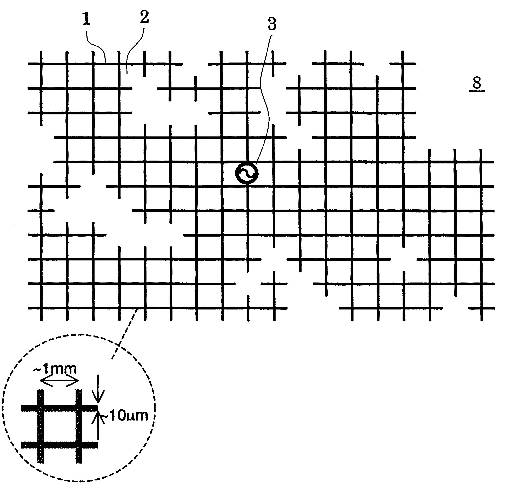
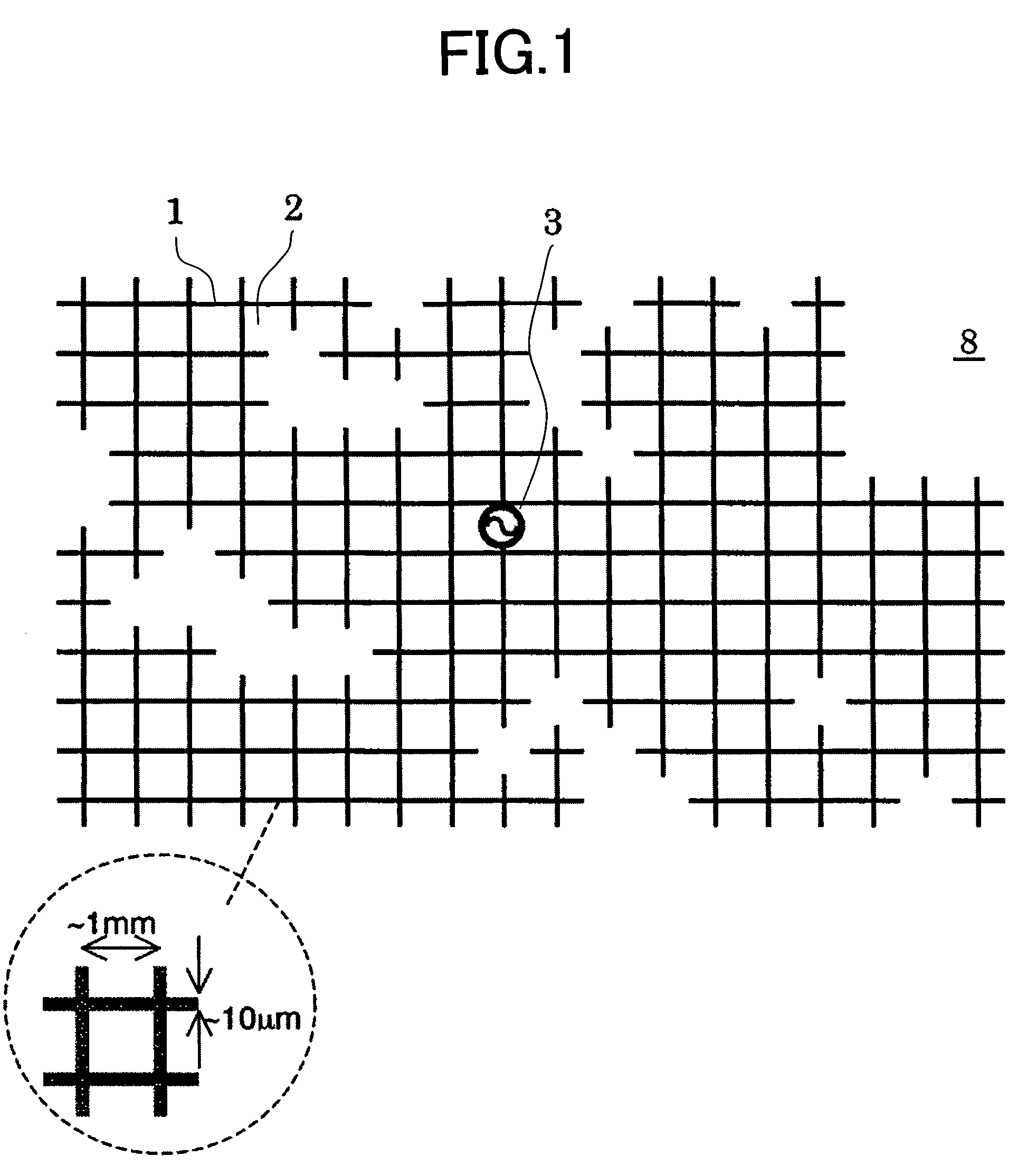
[0030]Now, an embodiment of the present invention will be described with reference to FIG. 1. FIG. 1 shows a structure of a skeleton equalizing antenna according to the embodiment of the present invention. In the skeleton equalizing antenna 8, a grid with different roughness and fineness provided around a feeding point 3 has a planar structure including linear conductors 1 and spacing 2 between the linear conductors.
[0031]That is, the antenna 8 of the present embodiment is composed of a planar structure including the conductive grid which has roughness and fineness around the feeding point 3. The frequency spectrum viewed from the feeding point 3 of the antenna has two or more stationary points. In other words, in plural frequencies, the antenna 8 of the present embodiment has a structure which satisfies a desired feeding-point impedance matching condition.
[0032]In the planar structure of the antenna 8 of the present embodiment, a ratio of a width for constituting the conductor grid...
embodiment 2
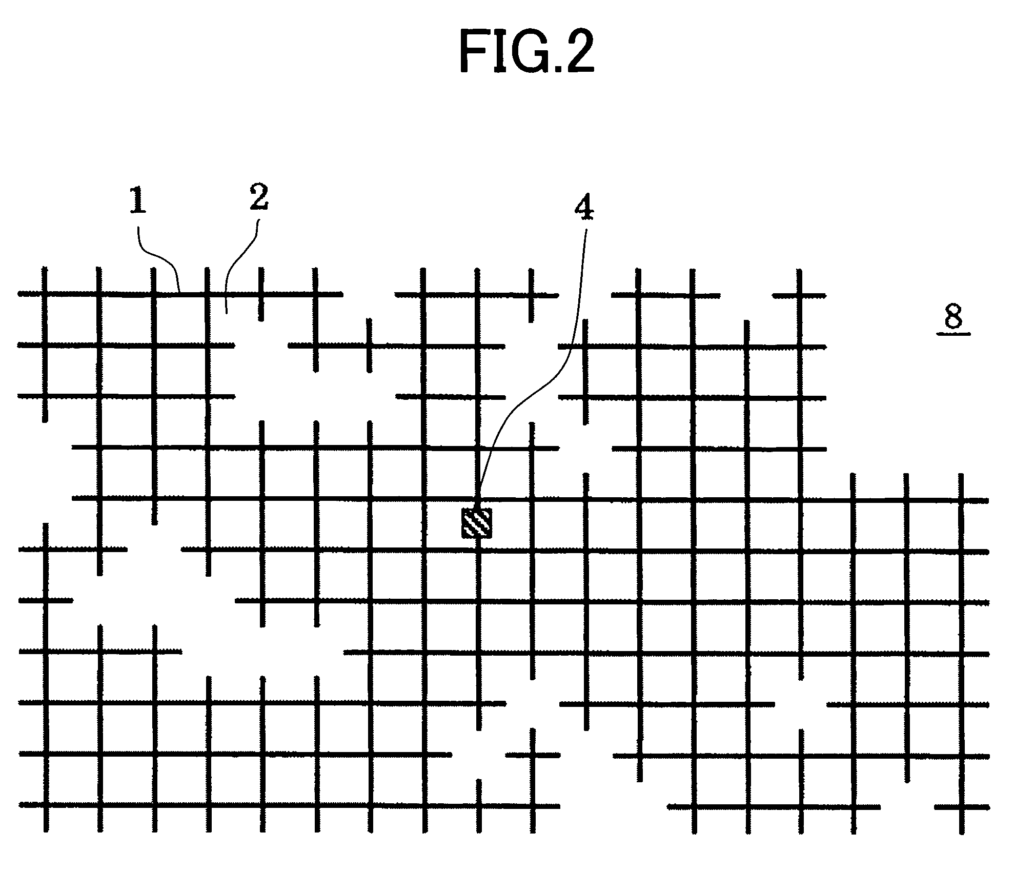
[0036]Referring to FIGS. 2 and 3, another embodiment of the present invention will be described. FIG. 2 shows a structure of an RFID tag using a skeleton equalizing antenna of the present invention. The structure is such that a high-frequency input / output point of the RFID chip 4 is connected to a feeding part 3 of the skeleton equalizing antenna 8. An example of a circuit diagram of the RFID chip 4 is shown in FIG. 3. The energy of electromagnetic waves transmitted from a base station through a skeleton equalizing antenna 41 is taken in, and is converted to a direct-current power supply in a rectifier circuit 42. A microprocessor 43 operated by the direct-current power supply drives a modulation circuit 44, modulation is applied on load impedance of the antenna 41, and the electromagnetic wave in which an amplitude of the received wave is modulated is emitted from the antenna 41.
[0037]According to the present embodiment, a circularly polarized antenna of a planar structure can be r...
embodiment 3
[0038]With reference to FIG. 4, another embodiment of the present invention will be described. FIG. 4 shows a configuration of another embodiment of the RFID tag using the skeleton equalizing antenna of the present invention. The present embodiment differs from the embodiment of FIG. 2 in that, besides the RFID chip 4, an electronic circuit 5 is provided inside the skeleton equalizing antenna. In general, the RFID chip includes an analog circuit and a digital circuit, and a high-frequency part of the analog circuit has a circuit which depends on a frequency in which the RFID tag operates. Since the circuit uses undulations peculiar to electromagnetic waves, there arises a need to use a transmission line, an inductive element, and a large capacity element. As a result, it is difficult to provide such a circuit inside the RFID which is physically restricted to a small region. These elements are replaced with circuitry using an electronic circuit in a conventional technology. However, ...
PUM
 Abstract
Description
Claims
Application Information
 - R&D
- Intellectual Property
- Life Sciences
- Materials
- Tech Scout
- Unparalleled Data Quality
- Higher Quality Content
- 60% Fewer Hallucinations
Browse by: Latest US Patents, China's latest patents, Technical Efficacy Thesaurus, Application Domain, Technology Topic, Popular Technical Reports.
© 2025 PatSnap. All rights reserved.Legal|Privacy policy|Modern Slavery Act Transparency Statement|Sitemap|About US| Contact US: help@patsnap.com


