
Parallel mechanism having two rotational and one translational degrees of freedom

a technology of rotational and translational degrees, applied in the direction of mechanical control devices, process and machine control, instruments, etc., can solve the problem of high inertia load generated during high speed, and achieve the effect of reducing the mass of the entire module, reducing the size of the holding bracket along the linear guide, and reducing the rigidity

Active Publication Date: 2010-09-14
TIANJIN UNIV
View PDF10 Cites 0 Cited by
  • Summary
  • Abstract
  • Description
  • Claims
  • Application Information

AI Technical Summary

Benefits of technology

The invention provides a small-sized parallel mechanism with two rotational and one translational degrees of freedom. The mechanism includes a holding bracket, a movable platform, and three branch joint assemblies. The branch joint assemblies each include a connecting rod, a linear guide, a driving device, and a carriage. The carriage connects to the holding bracket through a hinge with one rotational degree of freedom. The mechanism keeps two rotational and one translational degrees of freedom and reduces the size of the holding bracket and mass of the entire module. The technical effect is a compact and efficient parallel mechanism with reduced size and weight.

Problems solved by technology

In the aforementioned mechanism, as the linear guide is fixed on the holding bracket, a drawback arises: due to the large size of the holding bracket in the moving direction of the guide, high inertia load will be generated during high speed movement of the holding bracket along with the other moving components connected therewith.

Method used


Image

  • Parallel mechanism having two rotational and one translational degrees of freedom
  • Parallel mechanism having two rotational and one translational degrees of freedom

Examples


Embodiment Construction

[0008]Now detailed description of the invention is made in conjunction with the drawing and embodiments.

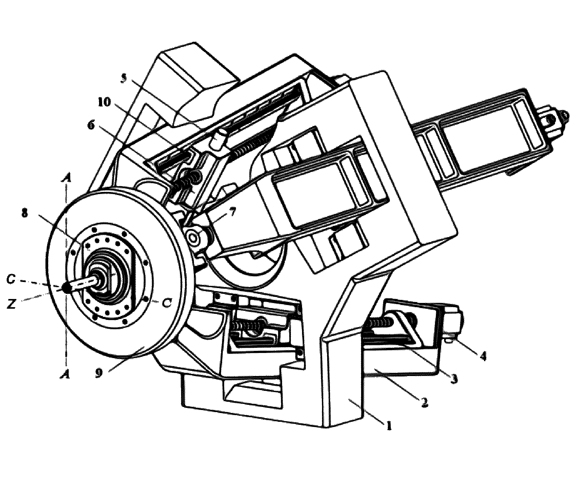
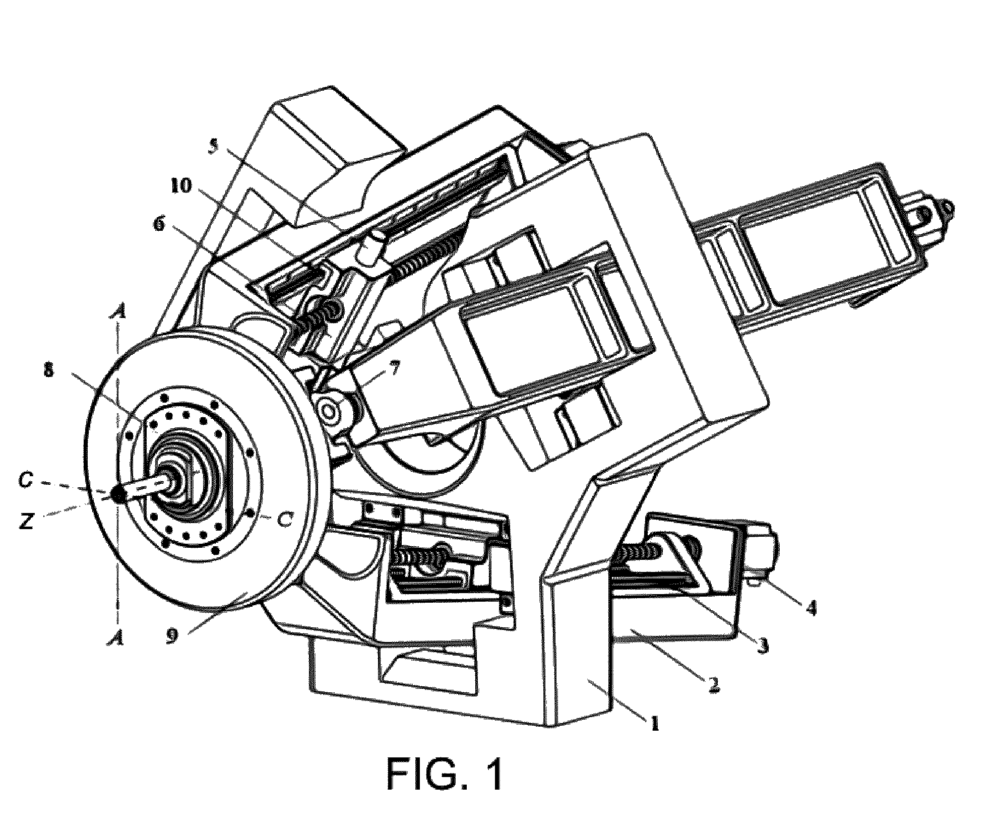
[0009]The two rotational and one translational parallel mechanism provided by the invention comprises a holding bracket 1, a movable platform 9 and three branch joint assemblies of the same construction uniformly disposed between the holding bracket land the movable platform 9 with Z axis as their symmetric axis, as shown in FIG. 1. Each branch joint assembly comprises a connecting rod 2, a linear guide 3, a driving device 4 and a carriage 6. Both the linear guide 3 and the driving device 4 are firmly secured onto the connecting rod 2. The branch joint assembly, the holding bracket 1 and the movable platform 9 are connected with each other by a suitable manner. One end of the connecting rod 2 is connected to the movable platform 9 through a hinge 7 which bears three rotational degrees of freedom and may be a ball hinge. A sliding joint 10 may be used to connect the carriage 6 and ...


PUM

PropertyMeasurementUnit
rotational degrees of freedomaaaaaaaaaa
rotational degree of freedomaaaaaaaaaa

Abstract

A parallel mechanism which has a holding bracket; a movable platform; and three branch joint assemblies of the same structure that are spatially arranged symmetrically about an axis disposed between the holding bracket and the movable platform. Each branch joint assembly has a connecting rod, a linear guide, a driving device and a carriage. The linear guide and the driving device both are secured on the connecting rod. One end of the connecting rod is connected with the movable platform through a hinge having three rotational degrees of freedom. The carriage and the linear guide are connected with each other by a sliding joint, and the carriage is connected with the holding bracket by a hinge having one rotational degree of freedom.

Description

FIELD OF THE INVENTION[0001]The invention is directed to a three coordinate's parallel robot mechanism and more particularly, is directed to spatial parallel mechanism capable of achieving two rotational and one translational degrees of freedom.BACKGROUND OF THE INVENTION[0002]It is known from such as U.S pat. No. 6,431,802 (or W00025976, EP1123175, CA2349579 and DE19850708) that prior art spatial two rotational and one translational parallel mechanism comprises a holding bracket, a movable platform and three branch joint assemblies of the same structure. The branch joint assemblies each consist of five components, i.e., a driving device, a linear guide, a carriage, a hinge and a connecting rod. The parallel mechanism is structurally symmetrical about an axis in space. An end-effector is mounted on the movable platform. The moving direction of the guide is parallel to the symmetrical axis and the carriage is attached to the linear guide via a sliding joint. The connecting rod has it...

Claims


Application Information

Patent Timeline
Patent Type & Authority Patents(United States)
IPC IPC(8): G05G11/00
CPCB25J17/0266Y10T409/308512Y10T409/307672Y10T74/20341Y10T409/308232Y10T409/309576Y10T409/307616
Inventor HUANG, TIANLIU, HAITAO
Owner TIANJIN UNIV
Learn More