Electrical transmission line repair device

a technology for transmission lines and repair devices, applied in the direction of line/current collector details, connection contact materials, connections effected by permanent deformation, etc., can solve the problems of aluminum connectors that are operated in corrosive environments, aluminum connectors that are operated at elevated thermal levels or improperly installed, and connectors that are beginning to fail at an alarming rate, etc., to restore the full mechanical integrity of the system easy and readily installed

Active Publication Date: 2010-09-14
CLASSIC CONNECTORS
View PDF14 Cites 19 Cited by
  • Summary
  • Abstract
  • Description
  • Claims
  • Application Information

AI Technical Summary

Benefits of technology

[0014]In accordance with another aspect of the present disclosure, an electrical connector repair device is provided. The device includes a first clamping end, a second clamping end and an intermediate portion. The first clamping end is configured to be clamped onto a first conductor section located on one side of the compromised connector, and the second clamping end is configured to be clamped onto a second conductor section located on the other side of the compromised connector. The device provides a path for electrical current therethrough and has sufficient strength to support the connector.
[0018]A further object of the present disclosure is a repair device that is easily and readily installed by a lineman, using a minimal amount of the tools readily available.
[0019]A further object of the present disclosure is a repair device that is easily and readily installed by a lineman, on an energized circuit with no need to de-energize said circuit.

Problems solved by technology

This aging effect can be accelerated by many factors, such as increased operation temperature, improper installation and adverse environmental conditions.
However, aluminum connectors that are operated in corrosive environments, at elevated thermal levels or those improperly installed, tend to fail in less than 25 years, sometimes in as little as 15 years, and often in as little as 5 years.
Currently, the connectors are beginning to fail at an alarming rate.
Consequently, these higher electrical current levels result in much higher conductor and connector temperatures.
Additionally, a number of these aluminum bodied tension connectors have particular thermal limitations, typically about 93° C. When the thermal limitation is exceeded, the tempered aluminum alloys anneal, resulting in a loss of tensile properties on an order of about 65% to 70% of their original ultimate design strength.
A great number of these types of connectors have already failed catastrophically due to operation of the line beyond their design limits.
Connectors that serve both as mechanical tension anchors and electrical connectors are particularly prone to fail catastrophically.
The failure of such connectors results in energized power lines falling into and onto the general public, power outages and in some cases, property damage or severe personal injury and death.
Another option is to replace the old conductors and connectors with new ones that operate at temperatures as high as 250° C. However, right of way for new structures has become increasingly difficult or impossible to obtain, and replacement of existing conductors and connectors is not economically justifiable when the existing conductor still may have 20 to 30 years of usable life.
This is an extremely expensive undertaking.
Installation of the single extended length connector is also an expensive and time consuming undertaking.
This is even more expensive, typically priced in the thousands of dollars per connector, and is obviously extremely dangerous.
While this addresses the electrical interface, it does not address the weakened mechanical condition of the connector.
Thus, there would still be a significant risk of mechanical failure.

Method used


Image

  • Electrical transmission line repair device
  • Electrical transmission line repair device
  • Electrical transmission line repair device

Examples


Embodiment Construction

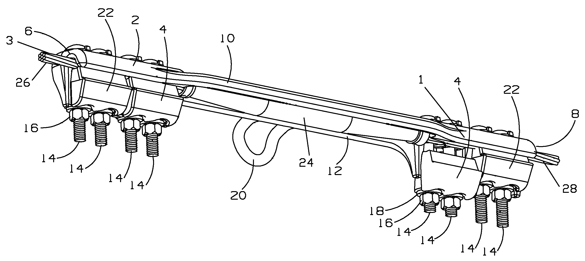
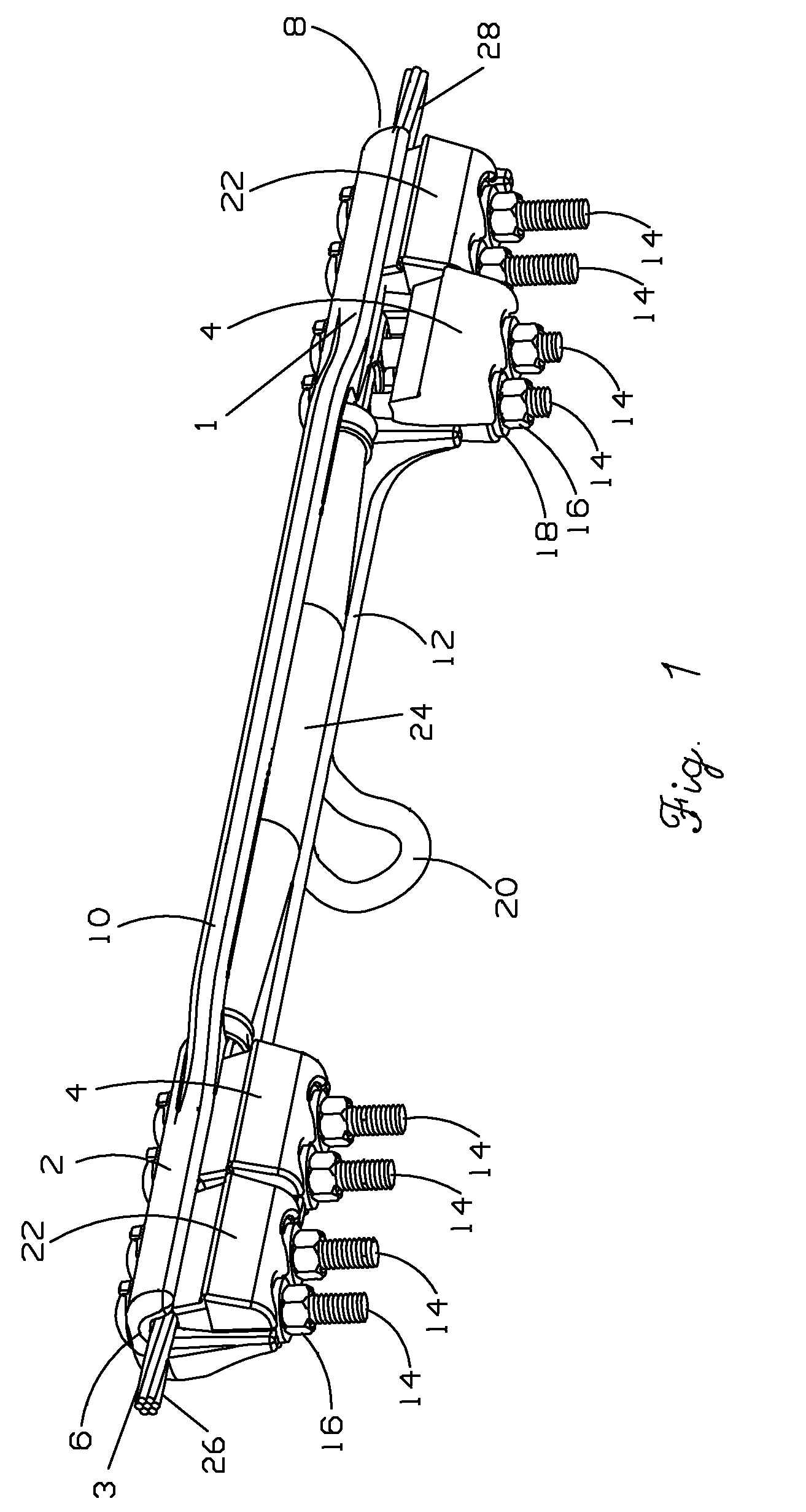
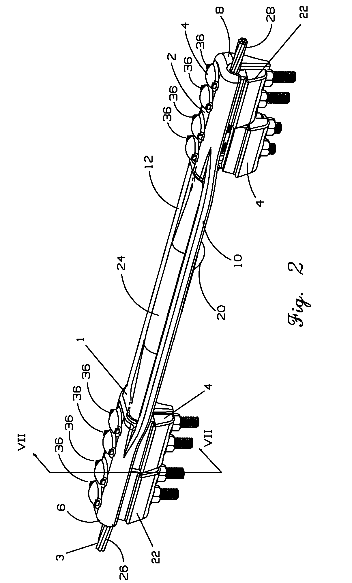
[0047]The repair or shunt devices described herein can be employed to restore the mechanical and electrical integrity of compromised sections of electrical transmission lines. Such compromised sections of transmission lines can include, but are not limited to, damaged or deteriorated conductors or connectors. Additionally, the devices can be used on connectors and conductors made from a variety of conductive materials, such as aluminum, copper or other metal alloys.

[0048]FIGS. 1, 2 and 4 show one embodiment of an electrical transmission line repair device 1 installed over a compromised section of electrical transmission line 3. In the illustrated example the compromised section is a deteriorated splice 24. Repair device 1 is installed onto the electrical transmission line 3 so that the device is attached to conductors 26 and 28 which extend from splice 24. Once the repair device is installed the splice 24 is nested within the device. When installed, repair device 1 concurrently serv...


PUM

PropertyMeasurementUnit
temperaturesaaaaaaaaaa
electrically conductiveaaaaaaaaaa
flexibleaaaaaaaaaa

Abstract

An electrical conductor repair device for restoring mechanical and electrical integrity to a compromised section of an electrical conductor. The device includes a body that serves as an electrical shunt and a mechanical support. The body includes a first end section for attachment to the conductor at a location on one side of the compromised section, and a second end section for attachment to the conductor at a location on the other side of the compromised section. The end sections are connected by an intermediate section.

Description

FIELD OF THE INVENTION[0001]The present disclosure generally relates to electrical transmission and distribution line repair and reinforcement devices. In particular, the present disclosure relates to devices that restore mechanical and / or electrical integrity to electrical conductors, connectors and clamps of a transmission or distribution system.BACKGROUND OF THE INVENTION[0002]Electrical transmission and distribution systems of the common overhead type include a plurality of electrical conductors. The electrical conductors are typically bare and are supported by insulating means attached to a pole or other suitable structure to suspend or support the conductors a safe distance above the reach of normal ground traffic and machinery. A variety of connectors are employed in the construction of such systems including splices, dead-ends, taps and terminals. Of these, splices and dead-end connectors are utilized in tension applications. Such connectors provide not only electrical conti...

Claims


Application Information

Patent Timeline
Patent Type & Authority Patents(United States)
IPC IPC(8): H01R11/09
CPCH01R4/44H01R4/62H01R43/00Y10T29/49194
Inventor GOCH, WAYMON P.
Owner CLASSIC CONNECTORS
Why Eureka
Try Eureka