Tissue transplantation method and apparatus

a tissue and apparatus technology, applied in the field of tissue transplantation, can solve the problems of inability to perform the procedure in time, inconvenient operation, and inability to centrifuge the fat, so as to reduce the need for centrifugation or minimize the effect of the need for fat removal

Active Publication Date: 2010-09-14
SHIPPERT ENTERPRISES
View PDF72 Cites 65 Cited by
  • Summary
  • Abstract
  • Description
  • Claims
  • Application Information

AI Technical Summary

Benefits of technology

[0016]In accordance with embodiments of the present invention, tissue transplantation methods and apparatuses are provided in connection with the removal of tissue from a donor site, the processing of that tissue, and the reinjection of that tissue into a recipient site. Furthermore, embodiments of the present invention eliminate or minimize the need for centrifuging of removed fats and other processing steps that have been part of the conventional tissue transplantation process. More particularly, a perforated chamber is provided to collect fat and filter unwanted substances from that fat. In addition, the same perforated chamber used to collect removed fat provides a reservoir from which fat can be injected into the body. Accordingly, embodiments of the present invention eliminate the need to transfer fat between a number of different vessels in order to process that fat and prepare it for injection, allowing harvest, separation, treatment and reinjection through the same syringe body.
[0020]In accordance with still other embodiments of the present invention, the end plug of the perforated inner chamber (or the integrated plug unit for embodiments including an integrated plug unit) may incorporate an inner suction tube having a number of perforations. The inner suction tube may be used to increase the effective filtering surface of the inner chamber and allow fluids and other matter to be drawn from collected fat from the center of the perforated chamber. In accordance with further embodiments, the end plug of the perforated inner chamber (or the integrated plug unit for embodiments including an integrated plug unit) may be fitted with an absorbent material to assist in the separation of such material from collected fat.
[0023]In accordance with embodiments of the present invention, a method for tissue transplantation is provided according to which tissue removed from a donor site using a cannula is collected in a perforated chamber. The same vacuum used to collect the tissue in the perforated chamber draws unwanted liquids and other matter away from the collected fat. The perforated inner chamber can then be removed from the outer chamber, the perforations can be blocked using a sleeve, and a plug in the proximal end of the perforated inner chamber can be removed. By interconnecting a needle to the distal end of the perforated inner chamber, and by inserting a plunger into the proximal end of the perforated inner chamber, fat can be reinjected directly from the perforated inner chamber. Accordingly, no intermediate steps that involve removing the fat from the perforated inner chamber are required for processing or to otherwise prepare the fat for reinjection.

Problems solved by technology

However, the use of fat was not very successful, because the instruments and techniques were not sufficiently refined.
These substances have proved effective at filling small areas, but the cost for larger areas has become prohibitive.
However, the instruments and devices conventionally available to perform the procedure remain clumsy and ill-suited for the procedure.
As a result, the procedure has remained difficult to perform, cumbersome, time consuming, expensive and relatively unsuccessful.
For example, the conventional process employed in connection with microlipoinjection comprises about 10 steps, some of which can cause damage to a significant percentage of the fat cells.
However, sterility is difficult to maintain in connection with centrifuging, which is performed separately from the sterile operating field, and involves ancillary personnel.

Method used


Image

  • Tissue transplantation method and apparatus
  • Tissue transplantation method and apparatus
  • Tissue transplantation method and apparatus

Examples


Embodiment Construction

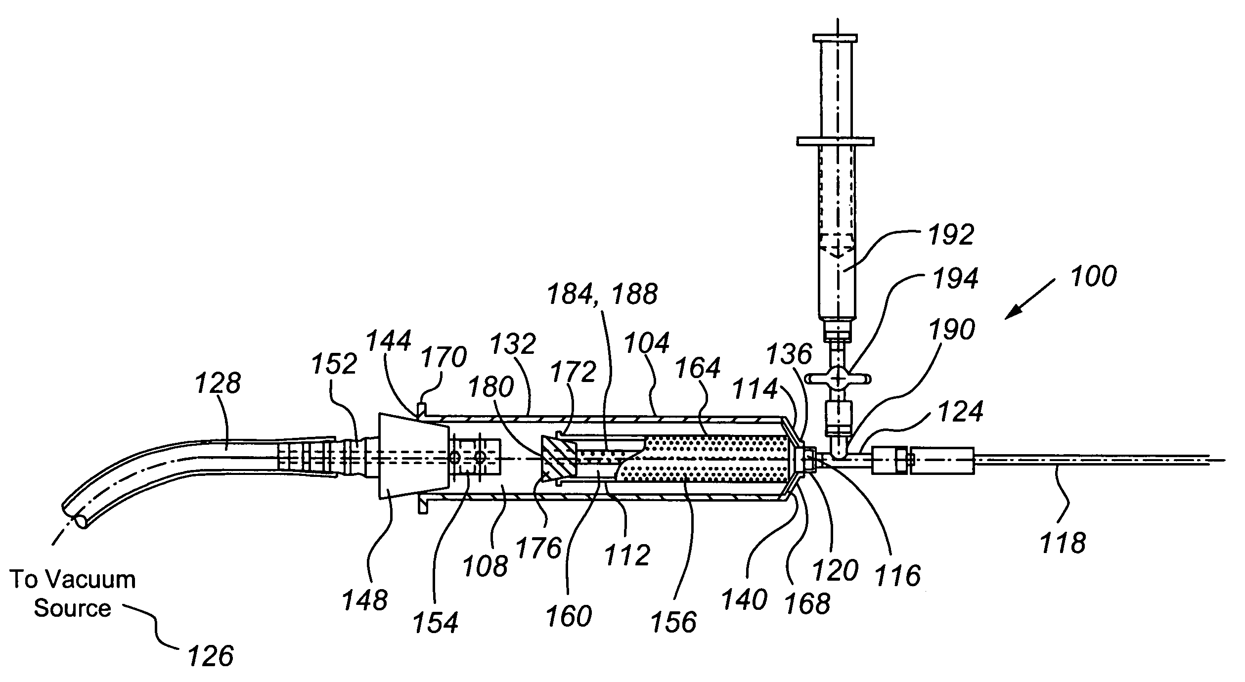
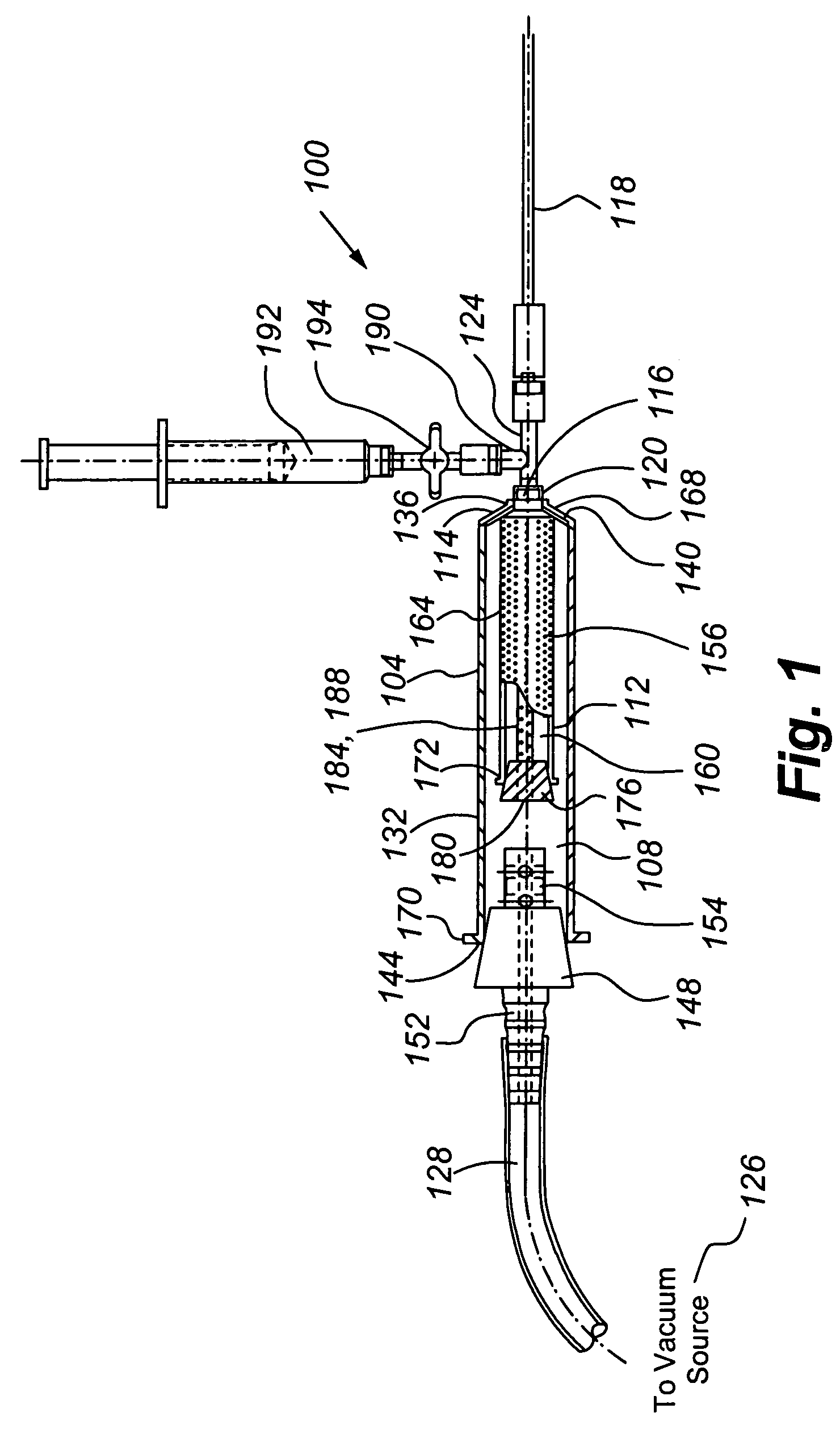
[0034]Embodiments of the present invention generally enable or facilitate tissue transplantation in accordance with a number of tissue transplantation principles, such as the following:

[0035](1) remove fat with a 12-gauge cannula for the best fat parcel size;

[0036](2) avoid requiring fat cells from traveling long tube distances;

[0037](3) maintain the suction at low or very low vacuum power (e.g., 8 to 12 inches of mercury);

[0038](4) use transfer conduits having uniform internal diameters and use transfer conduits having internal diameters that are as large as mechanically feasible;

[0039](5) avoid exposure of fat cells to air and light;

[0040](6) avoid exposing the fat cells to water or saline;

[0041](7) avoid vigorously mixing or shaking containers of donor fat cells while adding additives;

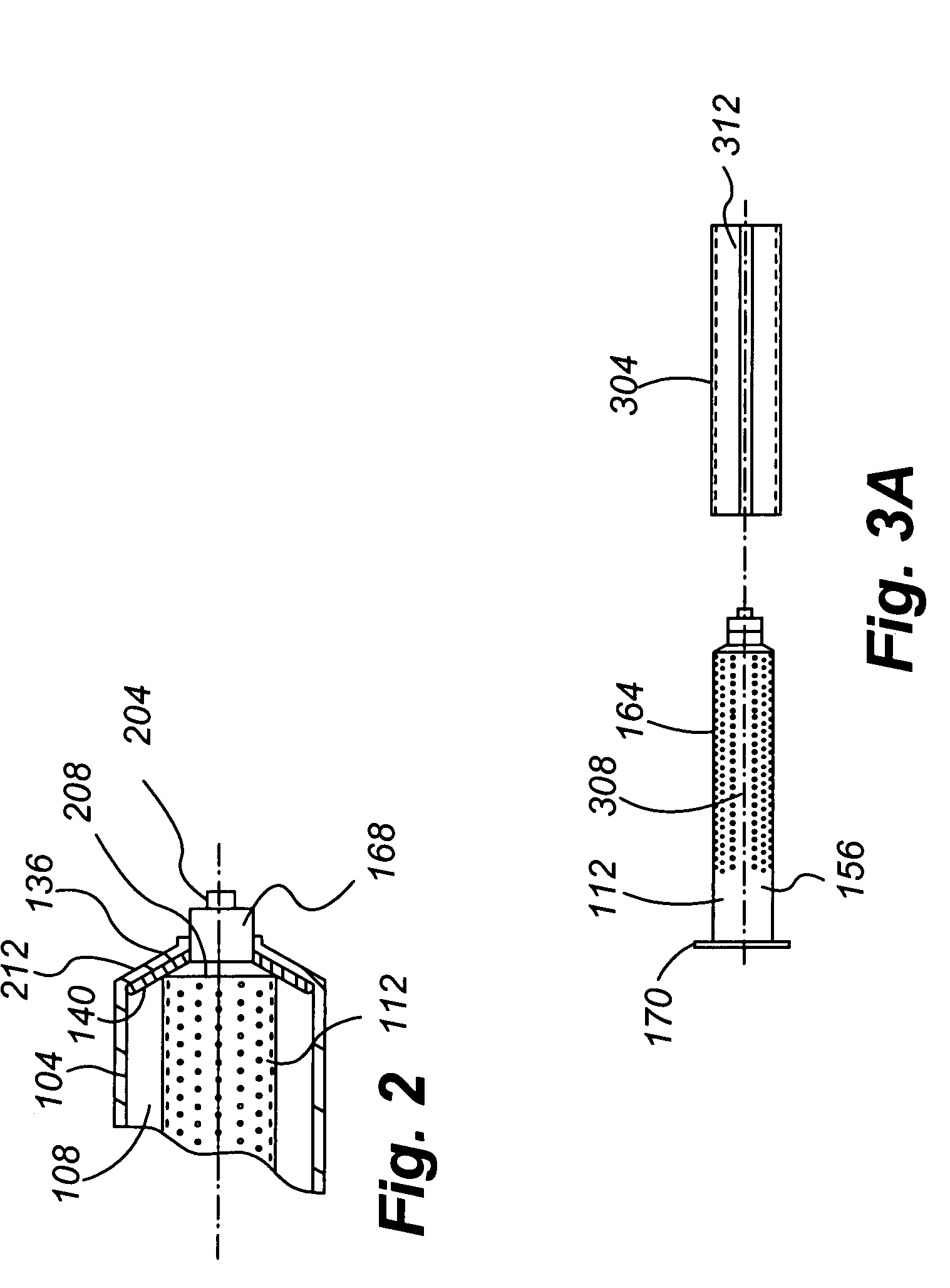
[0042](8) filter out blood, serum, anesthetic, dead fat cells and triglycerides from removed fat tissue;

[0043](9) treat removed fat tissue with additives to protect the liposite and potentially stim...


PUM


Abstract

The present invention provides for the transplantation of tissue from a donor site in a body to a recipient site. The device includes an outer chamber having an interior volume in which a perforated inner chamber can be placed. During the aspiration of tissue, a vacuum is formed in the interior volume of the outer chamber, to draw tissue from a cannula into the perforated inner chamber. The perforations are sized such that fat is collected within the inner chamber, while fluids and other materials are drawn through the perforations, away from the collected fat. For reinjection, the inner chamber can be removed from the outer chamber, and a sleeve positioned to cover the perforations and thereby form a syringe body that can be interconnected to a needle and plunger for reinjection of the collected fat.

Description

FIELD OF THE INVENTION[0001]The present invention is directed to the transplantation of tissue in bodies.BACKGROUND OF THE INVENTION[0002]Microlipoinjection is a process in which fat is taken by a cannula from one spot in the body and reinjected in another place in the body. Microlipoinjection has also been known as liposuction with fat transfer or fat transplantation. In general, microlipoinjection is performed to treat divots and scar indentations from trauma to the face or body, such as may occur as a secondary effect of domestic trauma, surgery or infection. Microlipoinjection can also be used to treat the effects of the loss of the subcutaneous layer of fat due to the normal aging process, either alone or in combination with facelift and fat grafting techniques. Microlipoinjection can also be used for providing filler to reapproximate weakened vocal chords, fill sinuses, or partially close incompetent valves.[0003]Up to about 1990, there were few artificial filler substances av...

Claims


Application Information

Patent Timeline
Patent Type & Authority Patents(United States)
IPC IPC(8): A61M1/00
CPCA61M1/0062A61M1/0064A61B2017/00969A61M1/0056A61M2202/08A61M1/79A61M1/774A61M1/892A61M1/772
Inventor SHIPPERT, RONALD D.
Owner SHIPPERT ENTERPRISES
Why Eureka
Try Eureka