
Filter delivery system

a filter and filter technology, applied in the field of filter delivery system, can solve the problems of pulmonary embolism, life-threatening condition, and many existing vena cava filter routine problems, and achieve the effects of facilitating the loading of the vessel filter, reducing the fatigue of the material comprising the hook, and facilitating the deployment of the vessel filter

Active Publication Date: 2010-09-14
CR BARD INC
View PDF390 Cites 78 Cited by
  • Summary
  • Abstract
  • Description
  • Claims
  • Application Information

AI Technical Summary

Benefits of technology

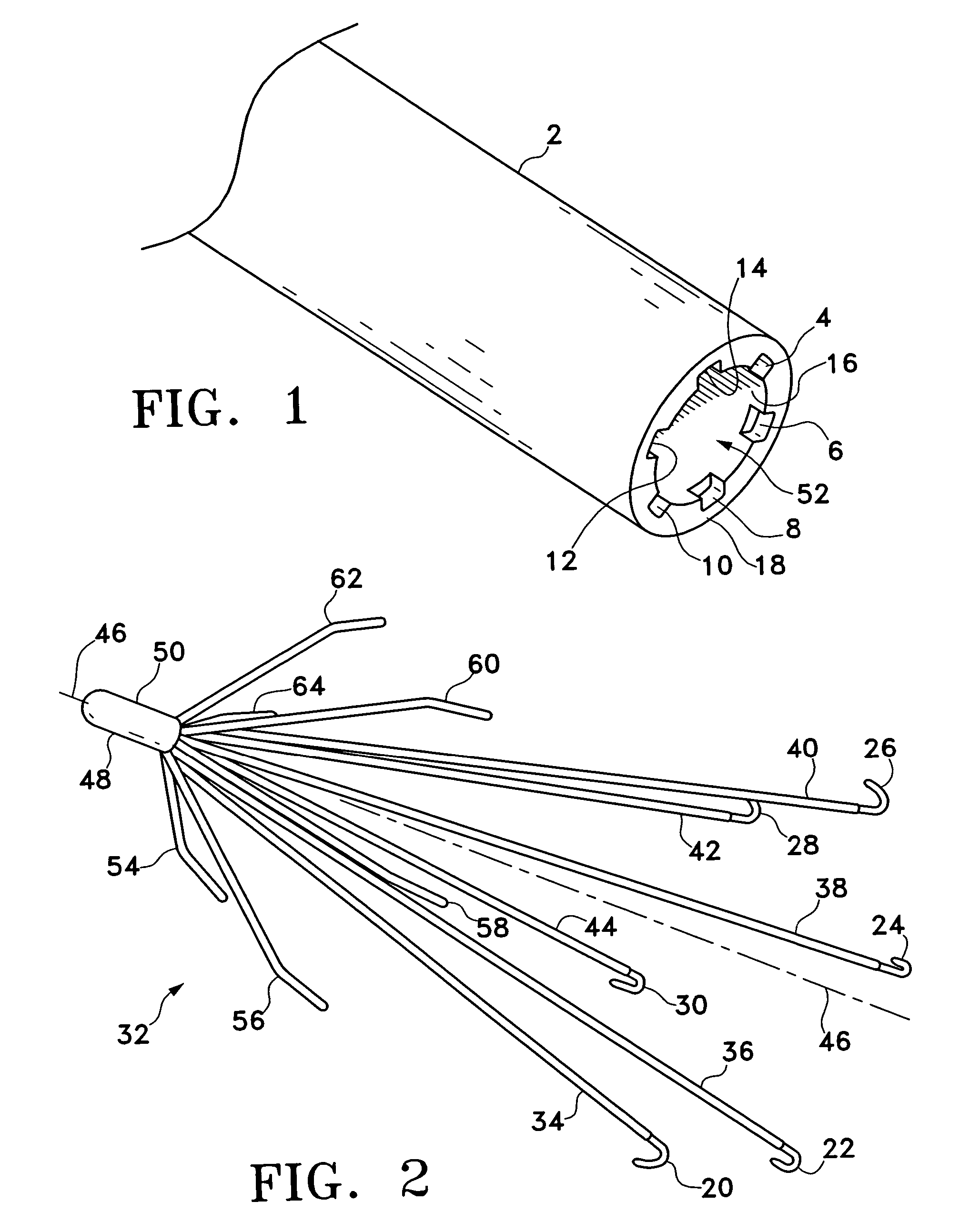
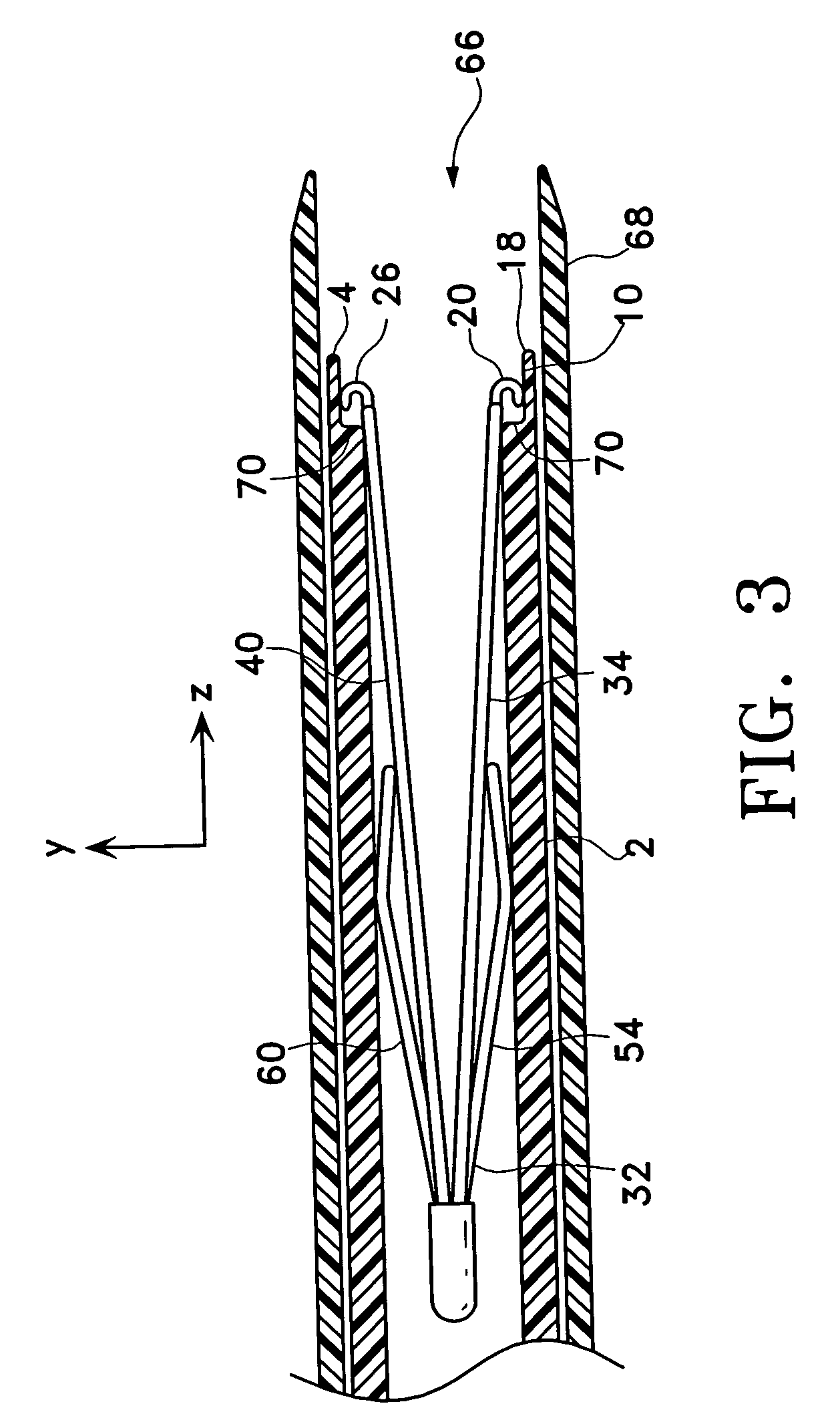
"The present invention is a vessel filter delivery device with a built-in mechanism to prevent hooks on the filter from interlocking and to prevent the filter from becoming entangled. The device includes an elongated catheter with grooves at the distal opening to separate the hooks on the filter. The device also includes a pusher-wire with a receptacle for holding and separating the hooks on the filter. The device improves the placement of the filter, reduces migration of the filter, minimizes fatigue of the hooks, and improves the deployment orientation and position of the filter. These features may lead to improved trapping of significant emboli, good vessel patency, limited thrombogenic response, and a decrease in the risk of hooks perforating the vessel wall."

Problems solved by technology

When the thrombus clot loosens from the site of formation and travels to the lung it may cause pulmonary embolism, a life-threatening condition.
Many of the existing vena cava filters routinely encounter problems during deployment due to entanglements of the radially expandable legs.
This is especially problematic in designs with hooks implemented on the radially expandable legs.
In the compressed / collapsed condition, the various hooks on the legs may interlock with other legs or hooks and render the device useless.

Method used


Image

  • Filter delivery system
  • Filter delivery system
  • Filter delivery system

Examples


Embodiment Construction

[0057]The following detailed description should be read with reference to the drawings, in which identical reference numbers refer to like elements through out the different figures. The drawings, which are not necessarily to scale, depict selected embodiments and are not intended to limit the scope of the invention. The detailed description illustrates by way of example, not by way of limitation, the principles of the invention. This description will clearly enable one skilled in the art to make and use the invention, and describes several embodiments, adaptations, variations, alternatives and uses of the invention, including what is presently believed to be the best mode of carrying out the invention.

[0058]Before describing the present invention, it is to be understood that unless otherwise indicated, this invention need not be limited to applications in humans. As one of ordinary skill in the art would appreciate, variations of the invention may be applied to other mammals as wel...


PUM


Abstract

A filter delivery device for implanting a vessel filter within a blood vessel of a patient's body. The filter delivery device includes a mechanism for preventing hooks and / or legs on a vessel filter from entangling with each other while the vessel filter is loaded within the delivery device. In one variation, the filter delivery device includes a delivery catheter with grooves at the distal end lumen opening. When a vessel filter with radially expanding legs is compressed and inserted into the distal end of the delivery catheter, the hooks on the distal end of the legs are received and separated by the corresponding grooves on the delivery catheter. In another variation, a pusher rod, with a receptacle for receiving the hooks, is positioned within a delivery catheter to prevent the entanglement of the hooks and / or legs of a filter loaded within the delivery catheter.

Description

CROSS-REFERENCE TO RELATED APPLICATIONS[0001]Not applicable.STATEMENT REGARDING FEDERALLY SPONSORED RESEARCH OR DEVELOPMENT[0002]Not applicable.REFERENCE TO A COMPACT DISK APPENDIX[0003]Not applicable.BACKGROUND OF THE INVENTION[0004]A vessel filter is a device inserted into a blood vessel to capture particles in the blood flow. Typically the device is inserted into a major vein to prevent a blood clot from reaching the lungs. Patients, who have recently suffered from trauma, have experienced a heart attack (myocardial infarction), or who have undergone major surgical procedure (e.g., surgical repair of a fractured hip, etc.) may have thrombosis in a deep vein. When the thrombus clot loosens from the site of formation and travels to the lung it may cause pulmonary embolism, a life-threatening condition. A vessel filter may be placed in the circulatory system to intercept the thrombi and prevent them from entering the lungs.[0005]Examples of various blood vessel filters and delivery ...

Claims


Application Information

Patent Timeline
Patent Type & Authority Patents(United States)
IPC IPC(8): A61M29/00
CPCA61F2/01A61F2002/011A61F2230/008A61F2230/005A61F2230/0067A61F2002/016A61F2/0105A61F2/011
Inventor TESSMER, ALEXANDER W.SPILKA, DAVID G.RAUCH, DAVID W.CHANDUSZKO, ANDRZEJ J.CARR, JR., ROBERT M.
Owner CR BARD INC
Learn More