Integrated compressor-tire sealant injection device with large mouth sealant container

a compressor and compressor technology, applied in the direction of liquid transfer devices, packaging goods types, liquid handling, etc., can solve the problems of increasing the cost of replacement, and introducing more problems and higher costs, so as to achieve more dispensing orientations.

Active Publication Date: 2010-09-21
ACCESSORIES MARKETING INC
View PDF24 Cites 67 Cited by
  • Summary
  • Abstract
  • Description
  • Claims
  • Application Information

AI Technical Summary

Benefits of technology

[0022]An integrated compressor and sealant container device is provided. The device fixes a tire puncture and inflates a tire via an integrated sealant container and compressed air source. The sealant container has a wide mouth that allows the outlet to be below most of the sealant fluid when the container is oriented on its side. The outlet is also below the sealant fluid when the jar is oriented vertically so that the outlet opening is below the sealant. Therefore use of a wide mouth jar allows more dispensing orientations than a narrow mouth bottle. The container has an air intake on one end and an outlet that is located as low as possible relative to the fluid being dispensed and oriented at the base of the container. The sealant container can be used with any compressor. The sealant container includes a hose and the hose has a unique valve which attaches to the tire valve to allow sealant and air to flow into the tire, but when disconnected / unscrewed from the tire, the valve closes and creates an air-tight seal. After use, the container and hose are simply discarded or recycled and a new sealant container may be simply inserted into the housing of the device. The device also permits compressed air only to be directed into the tire using a valve. The valve never contacts sealant (so it does not become clogged), never needs replacement and changes the system between “sealant and air” and “air only” modes. The sealant container may include check valves to seal the container. The sealant container does not use a metal or polymer seal so that no loose punctured seal fragments will compromise the user's tire valve and the tire valve will not leak from loose punctured seal fragments clogging it.

Problems solved by technology

It needlessly exposes the motorist to inherent roadside dangers for long time periods.
All of these solutions are sub-optimal and many introduce more problems and higher costs.
Spare tires for their part are bulky, heavy, expensive, difficult to access and difficult to install.
In fact, this method creates a more hazardous driving situation for the motorist.
There is not enough propellant in the aerosol sealant container to properly and safely inflate the tire.
Making this matter worse is the fact that the aerosol container becomes potentially explosive when stored in a vehicle operating in a climate where inside car temperatures can exceed 128 F. This can result in a very dangerous situation in which a partially inflated tire generates excessive heat due to repeated over-flexing which can cause the control of the vehicle to be compromised.
A partially inflated tire will also cause premature tire failure.
Potential advantages of this two part system have not been realized for various reasons.
This results in sealant being forced out of the container and into the tire through an exhaust.
The many systems tend to be complicated and potentially unreliable.
The narrow opening of the bottle restricts the orientation of the sealant delivery system.
Another disadvantage is hardening of the chemical sealant after use.
This is inconvenient for the user.
Replaceable parts increase design complexity.
This results in increased costs and lowered reliability.
This is at best inconvenient.
At worst, it can result in a user's vehicle being unrepaired.
Potential advantages of this design are not realized because of the requirement for fluid container orientation.
After use, the outlet of the device becomes contaminated with hardened sealant.
The combination of sealant container, cavity, and cap-valve increases complexity.
This complexity increases the cost of the device.
This complexity also reduces the system reliability.
This portion of the cap-valve becomes useless due to hardened sealant.
The container must be replaced after use and sometimes does not crush completely so that all of the sealant fluid is not delivered to the outlet and fluid that remains in the container is wasted.
Depending on the chemical composition of the fluid, this may be hazardous.
This is very inconvenient, complicated, and adds cost.
The container's metal or polymer seal requires puncturing before use and the device uses a fairly complicated piston puncturing device.
In addition, loose fragments of the punctured seal can be passed into the tire's valve core and this can result in the tire valve not functioning correctly so that air may leak from the tire while driving which negates any repair that may have been attempted.
However, this is not realized because the sealant container uses a narrow mouth so that the container must be oriented above the injection unit.
The container in this unit uses a metal or polymer seal and the seal must be punctured before injecting into a tire so that fragments of the punctured seal can impair the tire valve function which causes air to leak from the tire while driving after the sealant is injected which negates any repair that may have been attempted.
In addition, the sealant container must be connected just before injecting sealant in order to puncture the seal which is inconvenient for the user.
First, this device requires the user to connect the sealant container just before use (which is inconvenient for the user) and the sealant container must be pneumatically connected to the compressed air source.
Second, this device requires the user to screw the container into a special receptacle and the sealant container is a small mouthed bottle.
After attaching, the container is oriented so the opening is at the bottom and screwing the bottle onto the special receptacle punctures the seal so that loose fragments of the punctured seal can impair the tire valve function which may cause air to leak from the tire while driving after the sealant is injected which negates any repair that may have been attempted.
The base is the smallest face of the container so that orienting the device on the base causes it to be unstable and can fall over while sealant is dispensing.
In addition, if the user does not re-orient it, all the sealant will not dispense so that sealant is wasted.

Method used


Image

  • Integrated compressor-tire sealant injection device with large mouth sealant container
  • Integrated compressor-tire sealant injection device with large mouth sealant container
  • Integrated compressor-tire sealant injection device with large mouth sealant container

Examples


Embodiment Construction

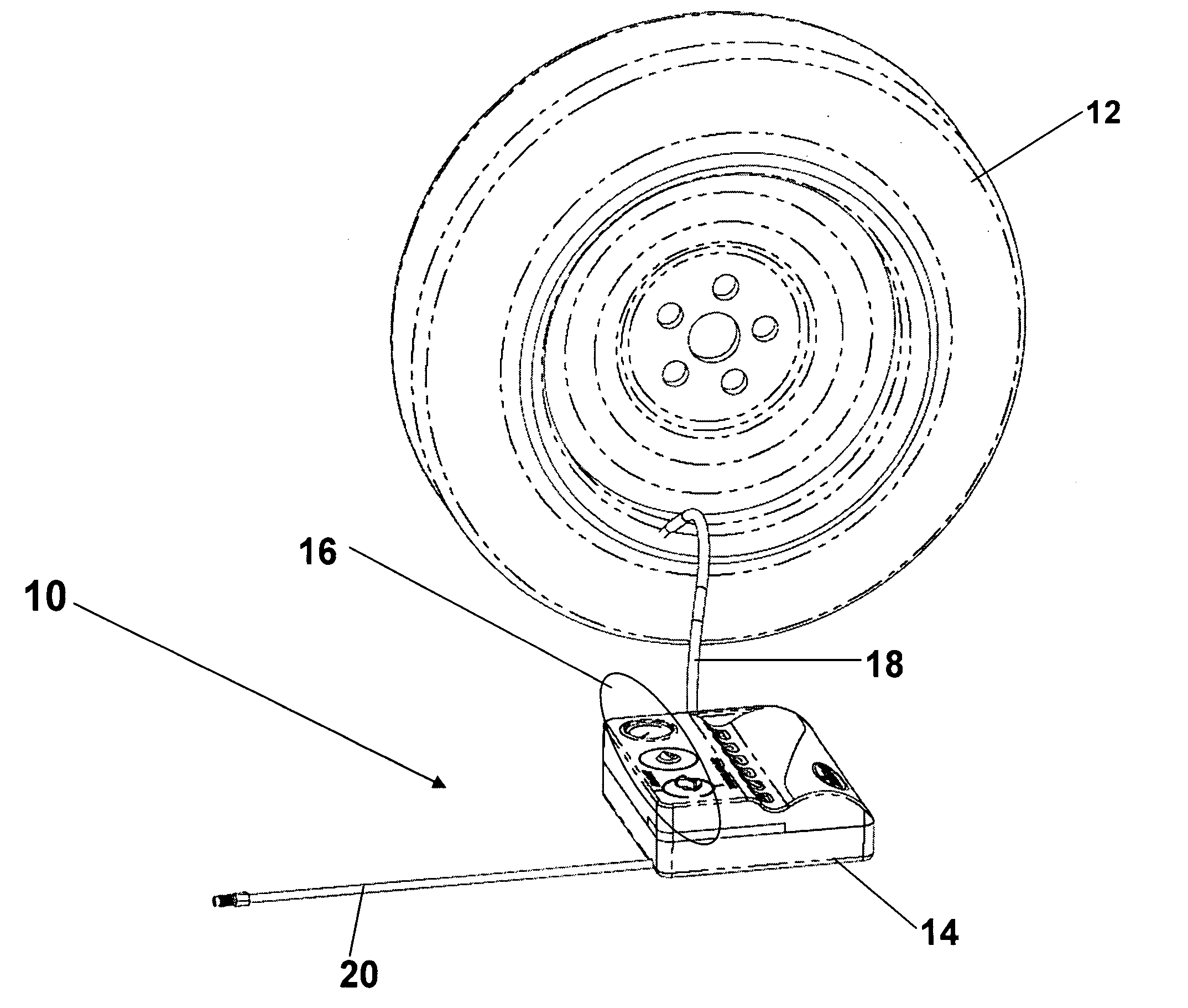
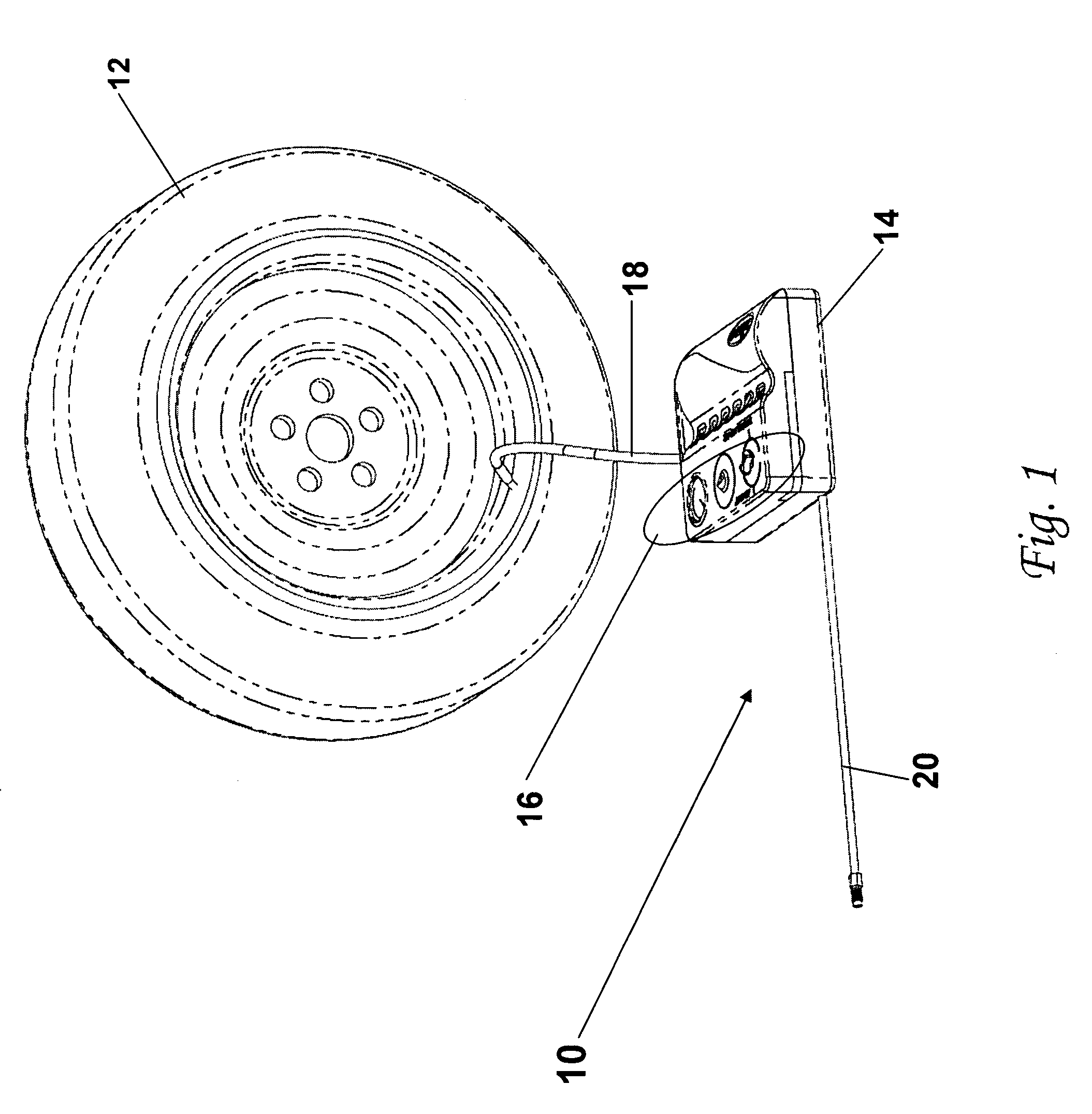
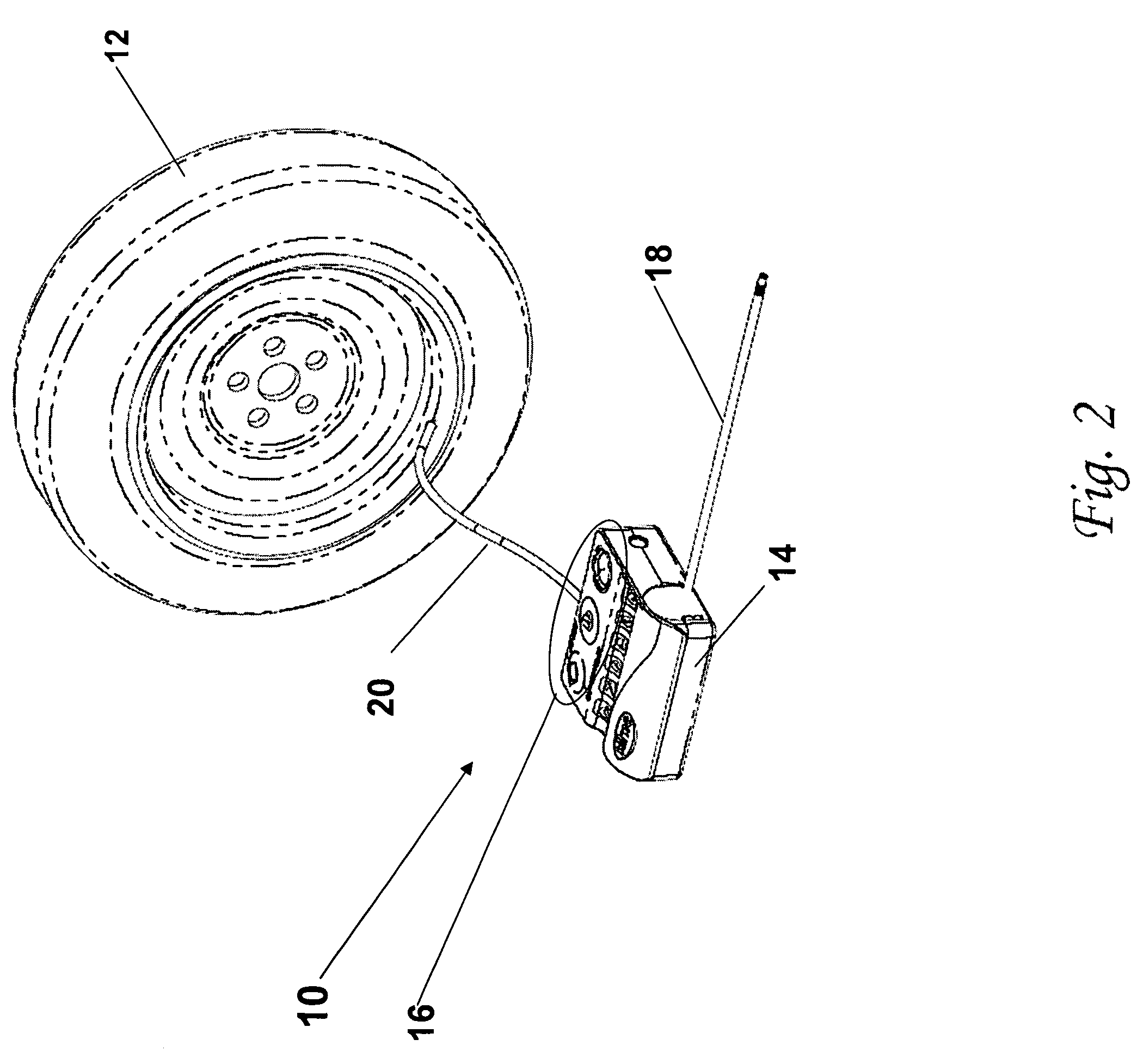
[0034]The invention is particularly applicable to an integrated compressor device and storage container that may be used to inflate and / or repair an automobile tire and it is in this context that the invention will be described. It will be appreciated, however, that the device and storage container in accordance with the invention has greater utility since it may be used to inflate and / or repair any type of inflatable member, such as a bicycle tire, a motorcycle tire or any other type of inflatable member that a person might want to inflate and / or repair.

[0035]FIGS. 1 and 2 illustrate an integrated compressor device 10 in accordance with the invention being used to seal and / or inflate an object 12, such as an automobile tire. The device 10 may include a housing 14 that houses an gas compressor and a sealant container that contains a sealant that may be propelled into the inflatable object 12 in order to repair a puncture in the inflatable object 12. The preferred gas compressor is a...


PUM

PropertyMeasurementUnit
pressureaaaaaaaaaa
timeaaaaaaaaaa
sizeaaaaaaaaaa

Abstract

An integrated compressor-tire sealant injection device with a sealant container and a compressor is provided. The integrated compressor-tire sealant injection device has a compressor unit that has a compressor and a connector to a bottle of sealant integrated into the compressor unit so that a bottle of sealant is connectable to the device to inflate a tire wherein the connector has first and second ball valves.

Description

FIELD OF THE INVENTION[0001]This invention relates to a tire repair and inflation device. It is intended to allow fast, simple repair and inflation of punctured pneumatic tires. It can be used as a compressor, dispensing air only. It can be used to dispense sealant and air. It has a replaceable sealant container.BACKGROUND OF THE INVENTION[0002]The fixing of a flat tire for most automobiles involves several steps including:[0003]1. Pulling safely to the side of the road.[0004]2. Locating the tools.[0005]3. Raising the vehicle.[0006]4. Replacing the punctured wheel assembly with a spare wheel assembly.[0007]5. Lowering the vehicle.[0008]6. Stowing the punctured wheel assembly.[0009]For the average motorist this task can be daunting at best. It needlessly exposes the motorist to inherent roadside dangers for long time periods. Over the past several years, the task of emergency tire repair has been addressed with a myriad of technologies. The traditional solution to an emergency flat t...

Claims


Application Information

Patent Timeline
Patent Type & Authority Patents(United States)
IPC IPC(8): B65B31/00B65B1/04B67D99/00
CPCB29C73/166B29L2030/00
Inventor CEGELSKI, JAMESHICKMAN, SCOTT NOBLE
Owner ACCESSORIES MARKETING INC
Why Eureka
Try Eureka