Airpot beverage dispenser and method

a beverage dispenser and air-type technology, applied in the direction of liquid handling, instruments, single-unit apparatuses, etc., can solve the problems of excessive heat loss, large contact of beverage, loss of steam,

Active Publication Date: 2010-09-21
FOOD EQUIP TECH
View PDF15 Cites 98 Cited by
  • Summary
  • Abstract
  • Description
  • Claims
  • Application Information

AI Technical Summary

Benefits of technology

[0014]Also, the objective is obtained by providing an airpot beverage dispenser with an insulated hollow body having, a bottom, an open top and a surrounding sidewall joining the open top to the bottom, a laterally extending, downwardly facing spout outside of the hollow body, and a feed tube with an outlet connected to the spout and an inlet within the hollow body and located adjacent the bottom for passing beverage from adjacent the bottom to the spout, with a brew-through assembly having a cover assembly mounted to the top of the hollow body and having a cover with an upwardly facing cover top and a bellows compartment having a bottom spaced beneath the cover top and protectively enclosing the bellows, an upwardly facing brew-through beverage inlet opening extending through the cover top and having a size substantially less than that of the top of the hollow body, and a beverage inlet passageway connected to the inlet opening and extending through the cover to a beverage outlet opening in the bottom for direct passage of freshly brewed beverage from the inlet beverage inlet through the beverage outlet and to within the hollow insulated body.
[0015]Additionally, the objective is partly achieved by providing an airpot beverage dispenser with an insulated hollow body having, a bottom, an open top and a surrounding sidewall joining the open top to the bottom, a laterally extending, downwardly facing spout outside of the hollow body and a feed tube with an outlet connected to the spout and an inlet within the hollow body and located adjacent the bottom for passing beverage from adjacent the bottom to the spout, with a cover assembly mounted to the open top of the hollow body and including an upwardly facing brew-through beverage inlet passageway passing through the cover and having an upwardly facing beverage inlet substantially smaller than that of the open top of the hollow body, and a feed tube and connected spout fixedly carried by the cover assembly at a location laterally spaced from the brew-through beverage inlet passageway, and means for permanently mounting the cover assembly to top of the hollow body.

Problems solved by technology

The inventors have determined that there are two basic problems with current airpot designs.
First, in all known airpot dispensers the cover that contains the bellows and carries the bellows actuator have no beverage inlets.
This disadvantageously results in wide contact of the beverage with the room temperature ambient air and excessive loss of heat from within the hollow body by upward air convection, loss of steam and unreflected infrared radiation from the beverage flowing through the open top.
This substantial heat loss continues throughout the period of filling the hollow dispenser.
However, because of known bellows designs, this approach has never been applied to air pots.
The other problem with known airpot dispensers is that they lack any reliable and hygienic means for determining the amount of beverage remaining in the airpot hollow body after serving has commenced.
Disadvantageously, this results in substantial heat loss through the open top and a resultant reduction in the serving temperature of the beverage, as explained above.
In the aforementioned U.S. Pat. No. 4,290,537 of Chi-Jung a mechanical float mounted for movement within the hollow body is mechanically linked to a level indicator, but in addition to being mechanical, the mechanical display of level faces upwardly only and disadvantageously cannot be seen from the side and thus cannot be seen from any significant distance.
Moreover, undesirably, the cover is designed to be moved to enable filling of the hollow body through its open top and movement can only result in possible damage to the mechanical measuring devices and can only contribute to their inherent unreliability due to mechanical wear and tear.

Method used


Image

  • Airpot beverage dispenser and method
  • Airpot beverage dispenser and method
  • Airpot beverage dispenser and method

Examples


Embodiment Construction

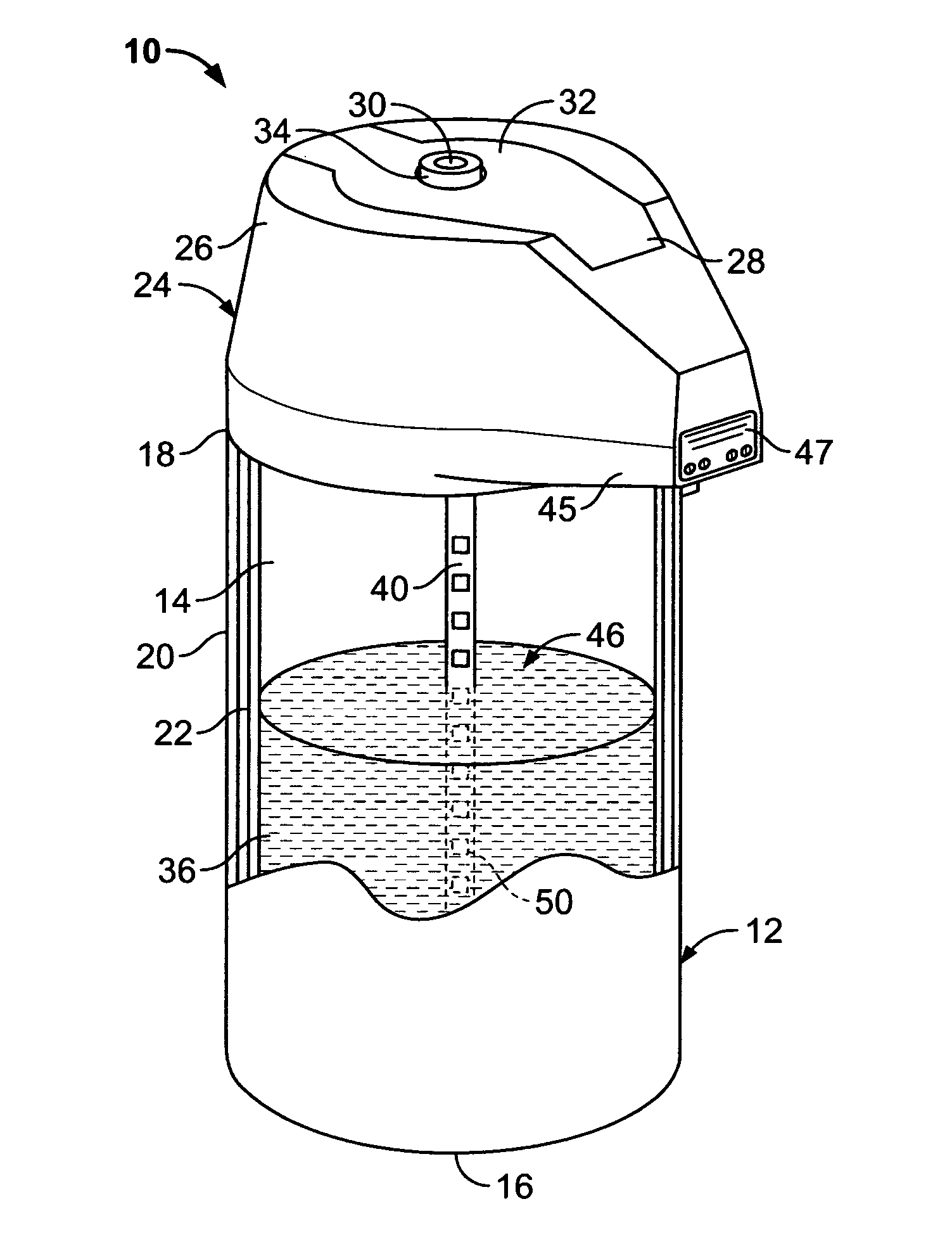
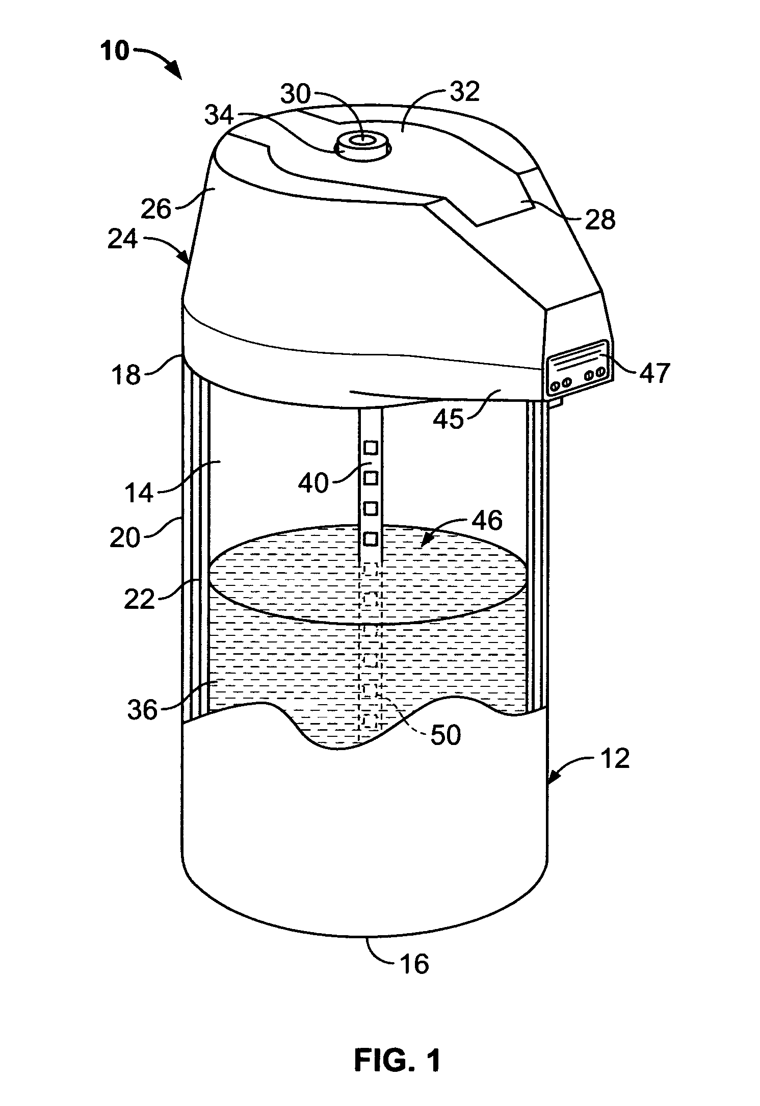
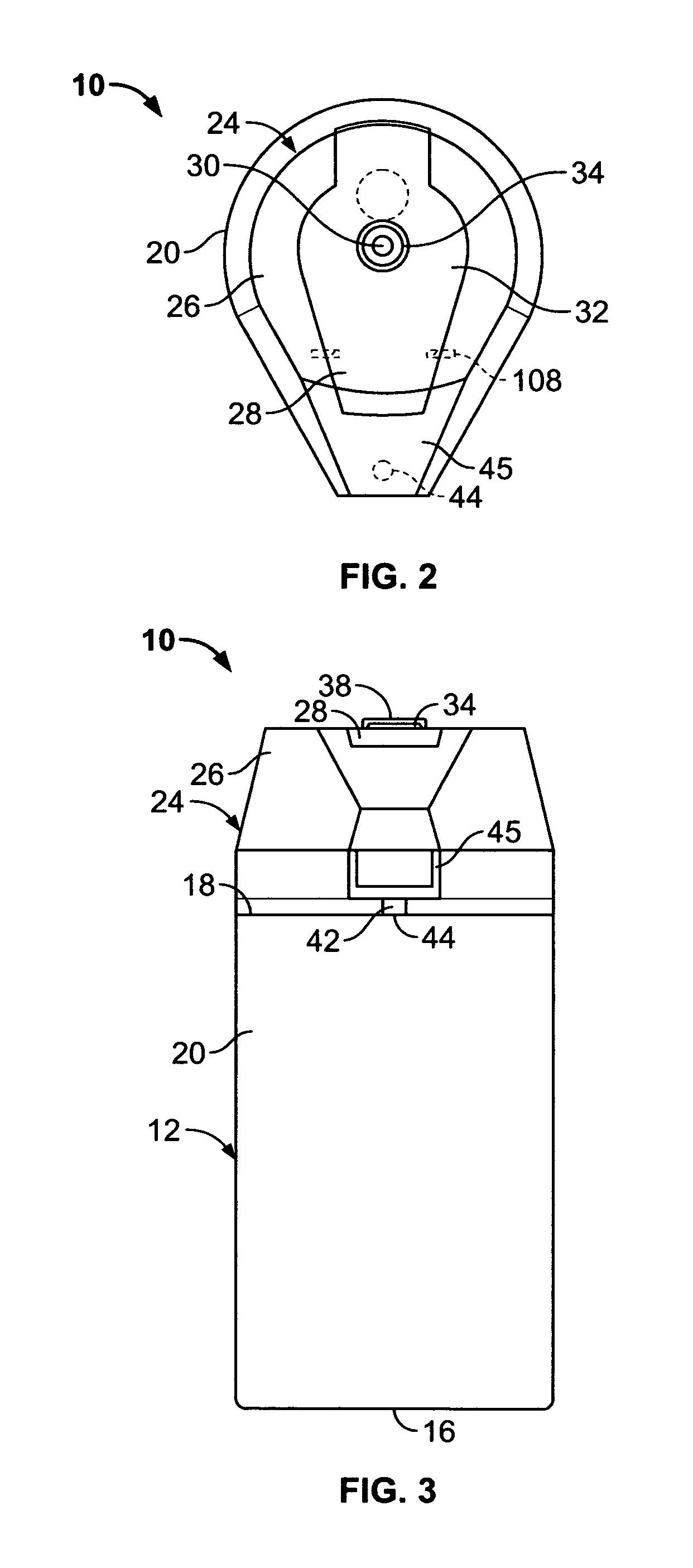
[0040]Referring now to FIGS. 1, 2 and 3, one embodiment of the airpot beverage dispenser 10 of the present invention has an insulated hollow body 12 having an interior 14 defined by a circular bottom 16, a circular open top 18 and a surrounding cylindrical sidewall 20 joining the top 18 to the bottom 16. The cylindrical sidewall 20 and the bottom 16 preferably have a double-walled construction of stainless steel with an evacuated gap 22 provided for insulation. The open top 18 is closed by a cover assembly 24 with fixed cover 26 and a movably cover member, or movably mounted cover, 28. A brew-through beverage inlet opening 30 in the movable cover member 28 is surrounded by an upraised collar 34. The cover body 24 substantially closes the open top 18 except for the brew-through inlet opening 30 that is substantially smaller than the open top 18. The relatively small size of the brew-through inlet reduces loss of heat from the beverage 14 during the brew cycle of an associated brewer ...


PUM


Abstract

An airpot beverage dispenser (10) having a composite dispense tube (40) with an exterior outlet (44) adjacent a top of a hollow body (20) and an interior inlet (110) located adjacent a bottom (16) for passing beverage (36) from adjacent the bottom (16) to the outlet when the interior of the hollow body (20) is pressurized has a brew-through assembly with a cover body (24) for substantially closing the open top (18) except for a centrally located brew-through passageway (95) substantially smaller than the open top (18) and extending between an upwardly facing exterior brew-through inlet (30) and an interior outlet (102) that passes through a central passageway extending through a double-walled bellows (74) or extends past a plurality of bellows (FIG. 16, 114) that are laterally spaced from the passageway has an electronic display (48) for indicating a plurality of levels of the beverage (36) within the hollow body and a resistive (FIGS. 11-14) or capacitive (FIG. 21) electronic level sensing assembly carried by the dispense tube (40) for sensing a plurality of different levels of beverage (36) within the hollow body and electrical leads (170, 172) printed on the dispense tube to pass the sensing signals to a display controller (127). The display, controller and portable power source (123) are protectively contained within a plastic watertight compartment (126) integrally formed with the cover body (24) is vented (FIG. 20) to prevent the accumulation of moisture within the compartment (126).

Description

CROSS-REFERENCE TO RELATED APPLICATIONS[0001]This application is a continuation-in-part of, and claims under 35 USC 120 the benefit of U.S. patent application Ser. No. 09 / 931,687 filed Aug. 16, 2001, now U.S. Pat. No. 6,741,180 issued May 25, 2004, which, in turn, claims under 35 U.S.C. 119(e) the benefit of provisional application Ser. No. 60 / 278,839 filed Mar. 26, 2001.BACKGROUND OF THE INVENTION[0002]1. Field of the Invention[0003]This invention generally relates to airpot beverage dispensers and methods of serving beverages, such as freshly brewed coffee, iced tea, lemonade, ice water, hot water and the like, from airpot beverage dispensers.[0004]2. Discussion of the Prior Art[0005]Airpot beverage dispensers of the type that have a insulated hollow body for storage of beverage and a pressurization system for forcing beverage to travel up a feed tube within the hollow body to a spout at the end of an open feed tube outside of the hollow body. Typically, the bellows is mounted wit...

Claims


Application Information

Patent Timeline
Patent Type & Authority Patents(United States)
IPC IPC(8): B65D37/00
CPCA47J41/0033B05B11/00B05B11/061B05B11/0097
Inventor WROBLEWSKI, LESZEK M.SOKOLSKI, BARTOSZLASSOTA, MICHAEL W.MICHALEK, CHRISTOPHER P.LASSOTA, ZBIGNIEW G.
Owner FOOD EQUIP TECH
Why Eureka
Try Eureka