Wireless system and method for displaying the path traveled by a marker

a marker and wireless technology, applied in the field of path tracing display apparatus, can solve the problems of inconvenient physical connection of wires or leads of the marker to a power source, inability to easily reuse, and inability to meet the needs of patients,

Active Publication Date: 2010-09-28
BLOOMFIELD SCI MUSEUM JERUSALEM
View PDF1 Cites 45 Cited by
  • Summary
  • Abstract
  • Description
  • Claims
  • Application Information

AI Technical Summary

Problems solved by technology

Moreover, a receiving medium such as paper is typically permanently marked by the marker and is not easily reused, and in order to trace multiple paths, paper must be replaced.
Where a permanent record of the path is not required, discarding used paper is both costly and wasteful.
However, wires or leads physically connecting the marker to a power source are inconvenient as they can become tangled, untidy and may limit the movement of the marker.
However the internal power supply itself eventually needs replacement.
Where continuous or repeated use of a path tracing apparatus is needed over long time periods, systems which require consumerables, such as paper, power sources and / or tracing materials, to be replenished may be impractical.

Method used


Image

  • Wireless system and method for displaying the path traveled by a marker
  • Wireless system and method for displaying the path traveled by a marker
  • Wireless system and method for displaying the path traveled by a marker

Examples


first embodiment

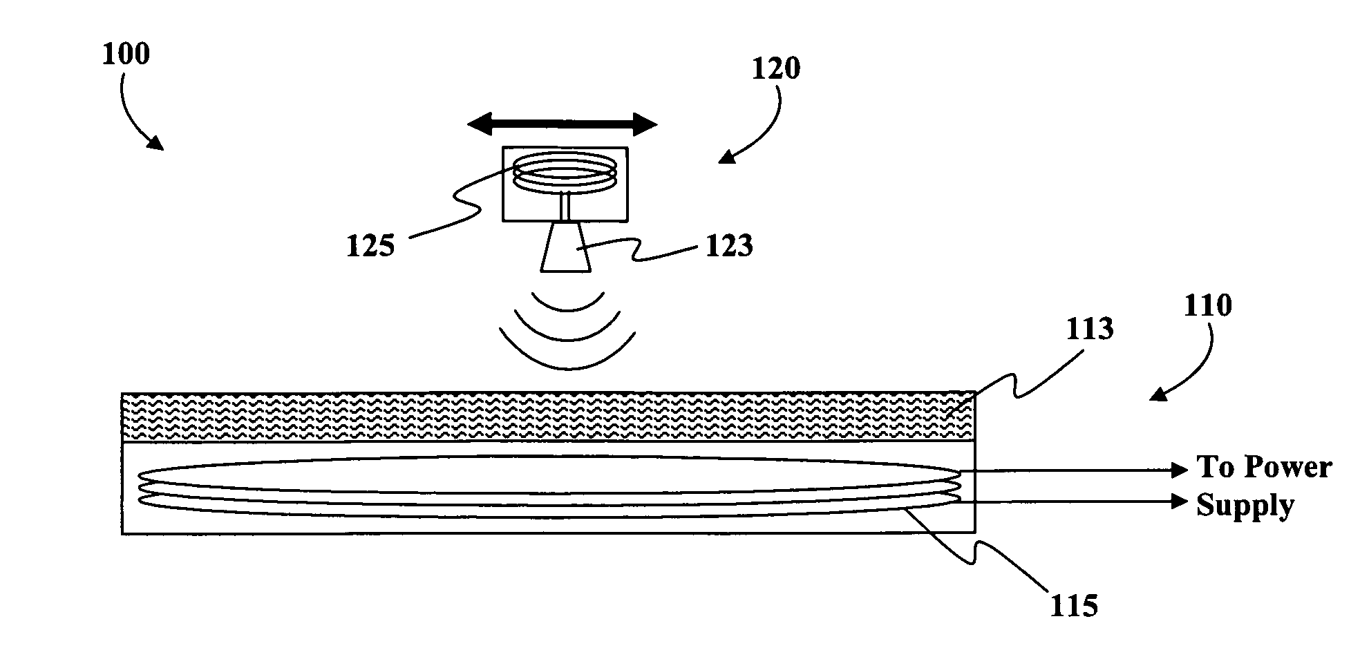
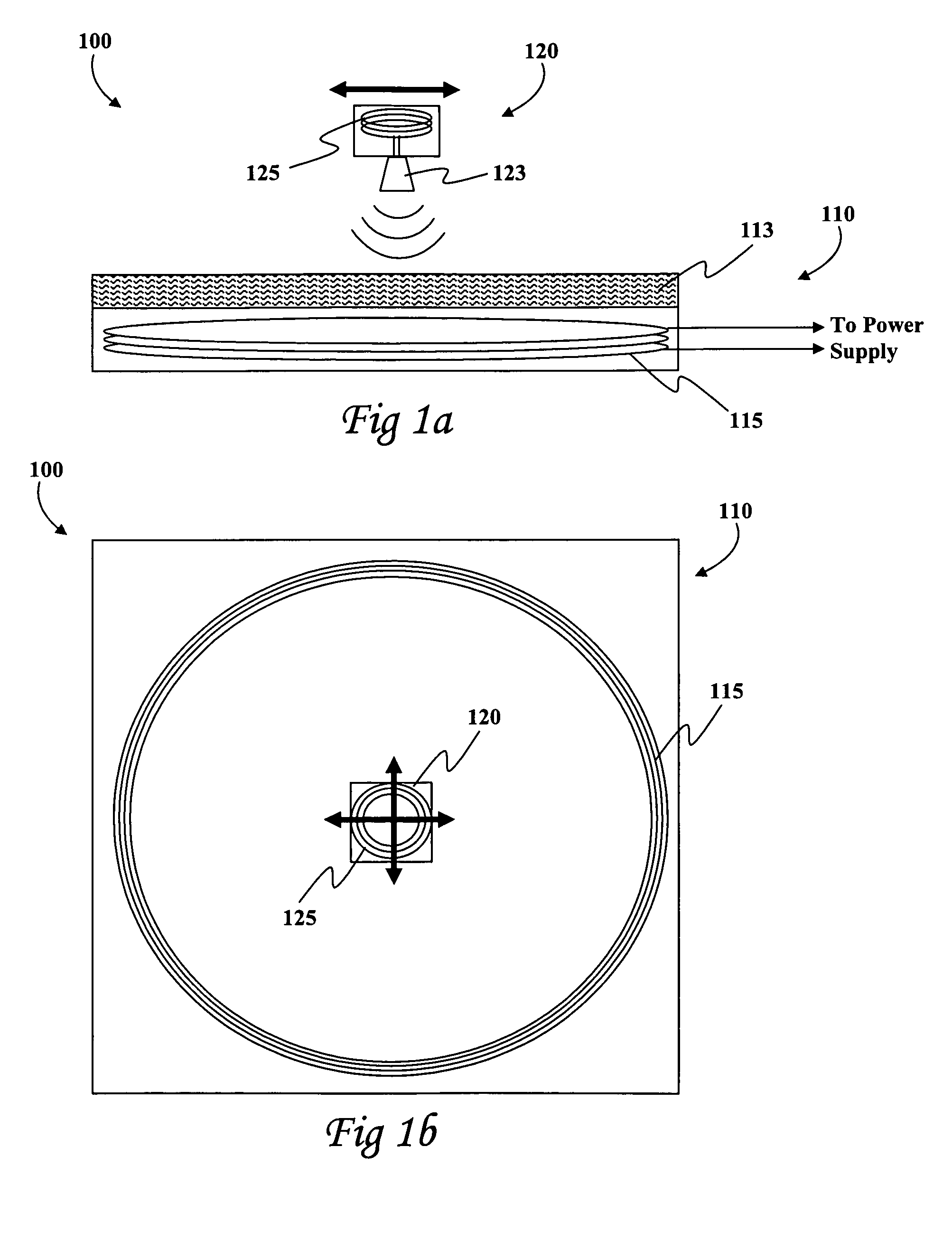
[0046]According the invention, power is provided to the emitter 123 via electromagnetic induction. The base unit 110 incorporates a primary inductive coil 115 which is connected to a power source, preferably via a driver (not shown). The driver may provide the electronics necessary to drive the primary coil 115. Driving electronics provides a high frequency oscillating voltage supply.

[0047]The mobile marker unit 120 further includes a secondary inductive coil 125 wired to the emitter 123. The secondary inductive coil 125 is configured to receive power via electromagnetic induction when it is within range of the primary inductive coil 115 of the base unit 110. It will be appreciated that no additional power source is typically required to power the emitter.

[0048]Although an inductively powered tracing device is described hereabove, it will be appreciated that alternative wireless power transfer may be used. For example:[0049]referring to FIG. 6a, a light source 6116 in the base unit ...

second embodiment

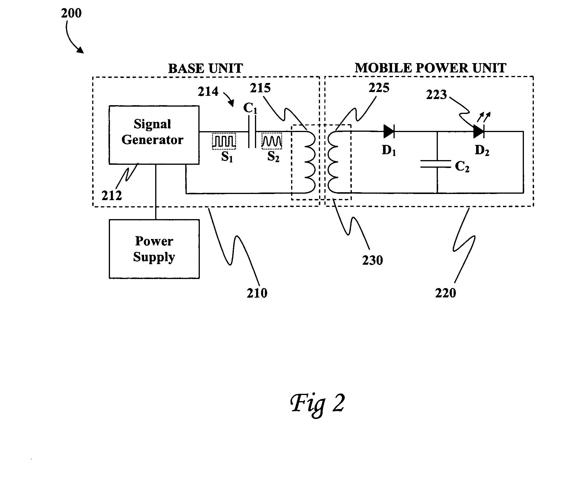
[0052]Referring now to FIG. 2, showing an exemplary circuit diagram of an inductive power providing arrangement 200 for transferring energy from a base unit 210 to a separate mobile power unit 220 according to the invention.

[0053]The base unit 210 includes a signal generator 212, a circuit 214 and a primary inductive coil 215. The signal generator 212 is wired to a power supply and configured and operable to provide a high frequency pulsed signal S1. According to one embodiment, the high frequency signal is within the range of about 30 kHz to 300 kHz. However, other frequencies may be effectively utilized. The circuit 214 includes a capacitor C1 which converts the pulsed signal S1 into a high frequency oscillating signal S2 which drives the primary coil 215.

[0054]The mobile power unit 220 is not mechanically connected to the base unit 210. The mobile power unit 220 includes a secondary coil 225, a smoothing capacitor C2 and a light emitting diode 223. The primary coil 215 and the se...

third embodiment

[0058]FIG. 4 shows a tracing apparatus 400 according to the invention for tracing the trajectory of FIG. 3 in a maintenance free manner. A primary coil 415 is embedded into a base unit 410 beneath the annular gear 412. The planetary gear 420 carries a secondary coil 425 which, when inductively coupled to the primary coil 415, serves as a mobile power unit 220 (FIG. 2), providing power to a LED 423 placed at point P.

[0059]The LED 423 is configured to emit a tracing signal toward a photosensitive receiving medium 413 coating the base unit 420. As the planetary gear 420 rolls around the annular gear 412, the trajectory 411 of the tracing signal is marked out along the receiving medium 413.

[0060]Moreover, particular photosensitive materials such as photochromic materials, photoluminescent materials, phosphorescent materials, thermochromic materials and polarizing materials have characteristic half-lives which determine the time taken for a mark to fade. The receiving medium 413 may be s...


PUM


Abstract

A low maintenance path tracing apparatus comprising at least one marker including an emitter of a tracer signal and a receiving medium for recording the path of the tracer signal. The apparatus further includes a power providing arrangement comprising a base unit which wirelessly provides power to the marker for powering the emitter.

Description

PRIORITY INFORMATION[0001]The present invention claims priority to U.S. Provisional Patent Application No. 60 / 924,217 filed on May 3, 2007.FIELD OF THE INVENTION[0002]The present invention generally relates to the field of path tracing display apparatus. More specifically the invention relates to path tracing apparatus having low maintenance requirements.BACKGROUND OF THE INVENTION[0003]It is often necessary to record the trajectory of a marker within a defined area. Such a record is useful for example in scientific experiments or demonstrations such as for recording the path of a pendulum, or the locus of a moving point, for example.[0004]Known methods for tracing the path of a marker include using paint brushes, drippers, crayons, writing implements and the like that mark some receiving medium such as paper, for example. In a first generic path tracing system, a tracing material such as a pigment, ink, dye or such like is carried by the marker and is deposited upon the receiving m...

Claims


Application Information

Patent Timeline
Patent Type & Authority Patents(United States)
IPC IPC(8): G21G5/00
CPCG01S1/70G06F3/0428
Inventor BEN-SHALOM, AMIRGREENWALD, OOLAMORRIS, MICHAELROFE, ARIK
Owner BLOOMFIELD SCI MUSEUM JERUSALEM
Why Eureka
Try Eureka