Method and apparatus for fluid influx detection while drilling

a technology of fluid influx and detection method, which is applied in the field of method and apparatus for fluid influx detection while drilling, can solve the problems of differential pressure sticking of drill pipe, decreased drilling rate, and loss of circulation

Active Publication Date: 2010-09-28
BAKER HUGHES HLDG LLC
View PDF15 Cites 7 Cited by
  • Summary
  • Abstract
  • Description
  • Claims
  • Application Information

AI Technical Summary

Problems solved by technology

Such influx of formation fluids may likely be the result of formation overpressures or abnormally high pressures.
Not only does the drilling rate decrease with a high overbalance of mud pressure versus formation pressure, but also lost circulation and differential pressure sticking of the drill pipe can readily occur.
More importantly, an underbalance of mud pressure versus formation pressure can cause a pressure “kick.” A well may kick without forewarning.
Balanced drilling techniques often require only a fine margin between effective pressure control and a threatened blowout.
Additionally, there are situations where underbalance is maintained to avoid formation damage so that it is important to detect inflow of formation liquids into the borehole.
All of these suffer from the drawback that the measurements are not available in real-time.
A drawback of methods that make density measurements is that gas must be present in sufficient quantities to affect the density of the mud, so that dissolved gas that may be a precursor to a gas kick would not register with density measuring devices.

Method used


Image

  • Method and apparatus for fluid influx detection while drilling
  • Method and apparatus for fluid influx detection while drilling
  • Method and apparatus for fluid influx detection while drilling

Examples


Embodiment Construction

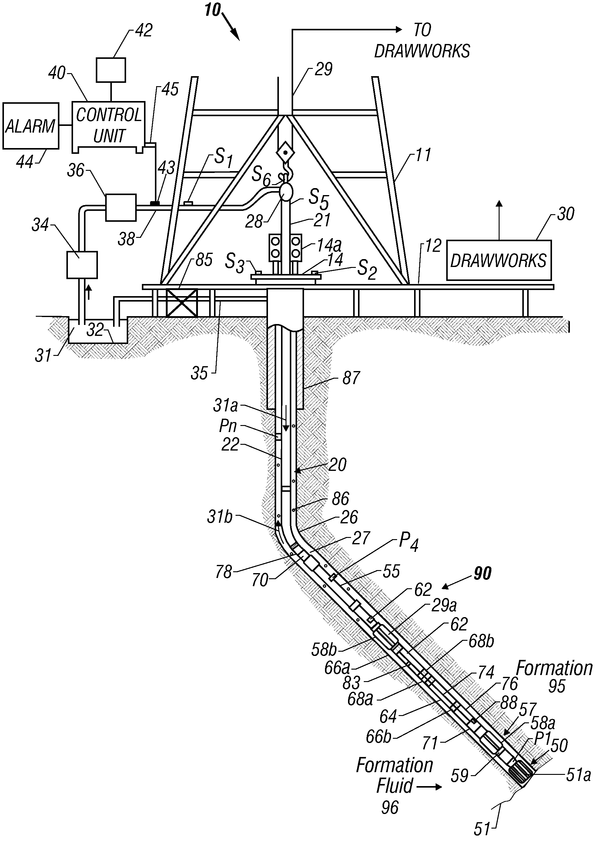
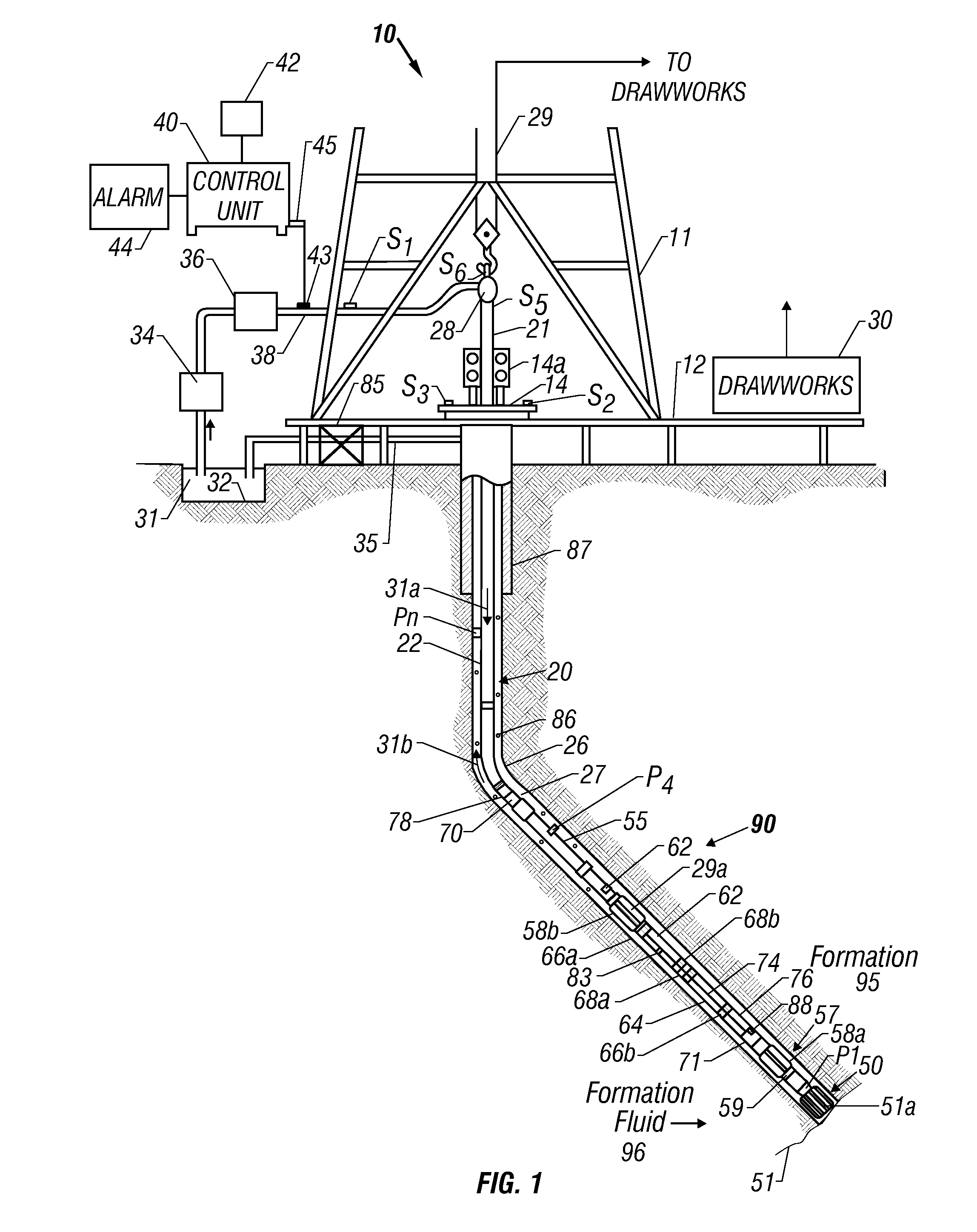
[0018]The present invention is described with reference to a drilling assembly, although many of the methods of the present invention are also applicable with logging tools conveyed on a wireline and may also be used in cased boreholes. FIG. 1 shows a schematic diagram of an exemplary drilling system 10 such as that disclosed by Estes. The drilling system has a bottom hole assembly (BHA) or drilling assembly 90 that includes gyroscope. For some of the applications of the present invention, a gyroscope is not essential. The BHA 90 is conveyed in a borehole 26. The drilling system 10 includes a conventional derrick 11 erected on a floor 12 which supports a rotary table 14 that is rotated by a prime mover such as an electric motor (not shown) at a desired rotational speed. The drill string 20 includes a tubing (drill pipe or coiled-tubing) 22 extending downward from the surface into the borehole 26. A drill bit 50, attached to the drill string 20 end, disintegrates the geological forma...


PUM


Abstract

A C / O ratio is determined using measurements of inelastically scattered gamma rays with a pulsed neutron source. Combined with look-up tables, the C / O measurement is used as an indicator of formation fluid influx into wellbore such as gas kick.

Description

CROSS-REFERENCES TO RELATED APPLICATIONS[0001]This application claims priority from U.S. Provisional Patent Application Ser. No. 60 / 750,868 filed on 16 Dec. 2005.BACKGROUND OF THE INVENTION[0002]This invention relates generally to oil and gas well logging tools. More particularly, this invention relates tools and methods for identifying the influx of formation fluids such as gas, oil, or water, into the borehole in real-time during drilling operations.[0003]Exploration for hydrocarbons commonly includes using a bottomhole assembly including a drill-bit for drilling a borehole in an earth formation. Drilling fluid or “mud” used in the drilling may vary in density or “mud weight” for a number of reasons. Such variations can result from changes in the quantity and density of cuttings (particles of formation); changes in the “mud program” at the surface, changes in temperature, etc. Variations in mud density also occur when gas or liquid enter the borehole from the formation. Such influ...

Claims


Application Information

Patent Timeline
Patent Type & Authority Patents(United States)
IPC IPC(8): G01V5/10G01V5/00E21B47/00
CPCE21B47/1015G01V5/104E21B47/11G01V5/102
Inventor GUO, PINGJUNDEO, PADMAKAR
Owner BAKER HUGHES HLDG LLC
Why Eureka
Try Eureka