Camera module and electronic device

a technology of electronic devices and cameras, applied in the field of cameras and electronic devices, can solve the problems of high cost of camera modules, unexpected short circuits, and reduced size of camera modules, and achieve the effect of low machining accuracy and high dimensional accuracy of the housing

Inactive Publication Date: 2010-09-28
KONICA MINOLTA OPTO
View PDF5 Cites 24 Cited by
  • Summary
  • Abstract
  • Description
  • Claims
  • Application Information

AI Technical Summary

Benefits of technology

[0010]In this configuration, the housing can be provided with electromagnetic shieldability and strength by resin molding with insertion of the metal plate. Details of a shape of the housing are defined by the resin having undergone the molding, and a high dimensional accuracy of the housing is thereby achieved even though the metal plate is a pressing with a low machining accuracy.

Problems solved by technology

There is a danger, however, that the use of conductive resin may cause unexpected short circuit.
There are problems in that the insulating members hinder reduction in size of the camera module and make the camera module expensive.
The covering of the optical unit and the imaging unit with the metal cover, however, makes it difficult to reduce a size of the camera module and makes the camera module expensive.
Though it would be desirable if a housing could be formed by press working of a metal plate, a sufficient machining accuracy cannot be attained by press working.
In an imaging unit having both small size and high performance, it is difficult to ensure the rigidity of the housing without increase in size thereof because the housing is often required to be composed of a single structural member and to be provided with a large opening for installation of a group of lenses and the like as well as for an optical path for imaging.

Method used


Image

  • Camera module and electronic device
  • Camera module and electronic device
  • Camera module and electronic device

Examples


first embodiment

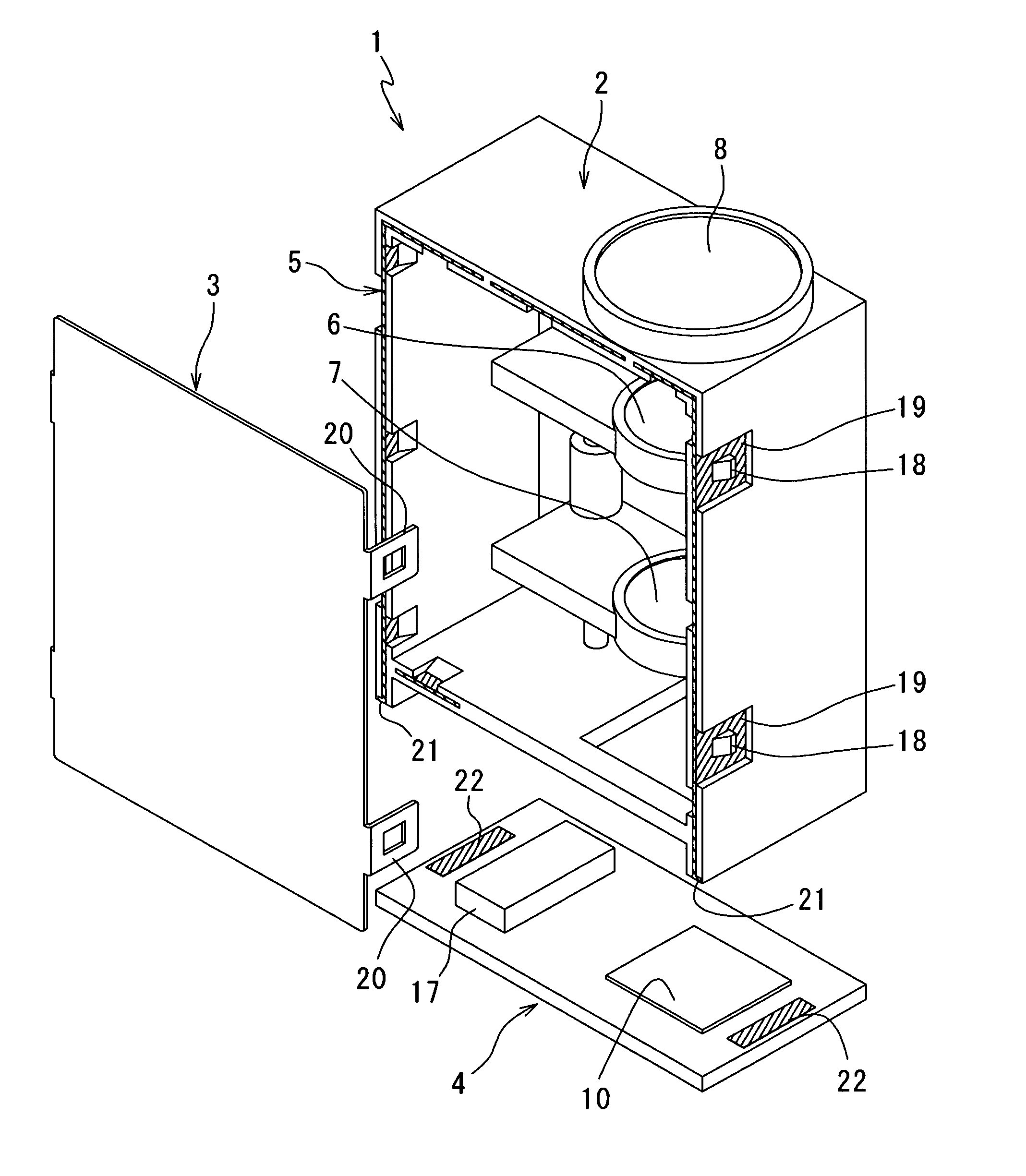
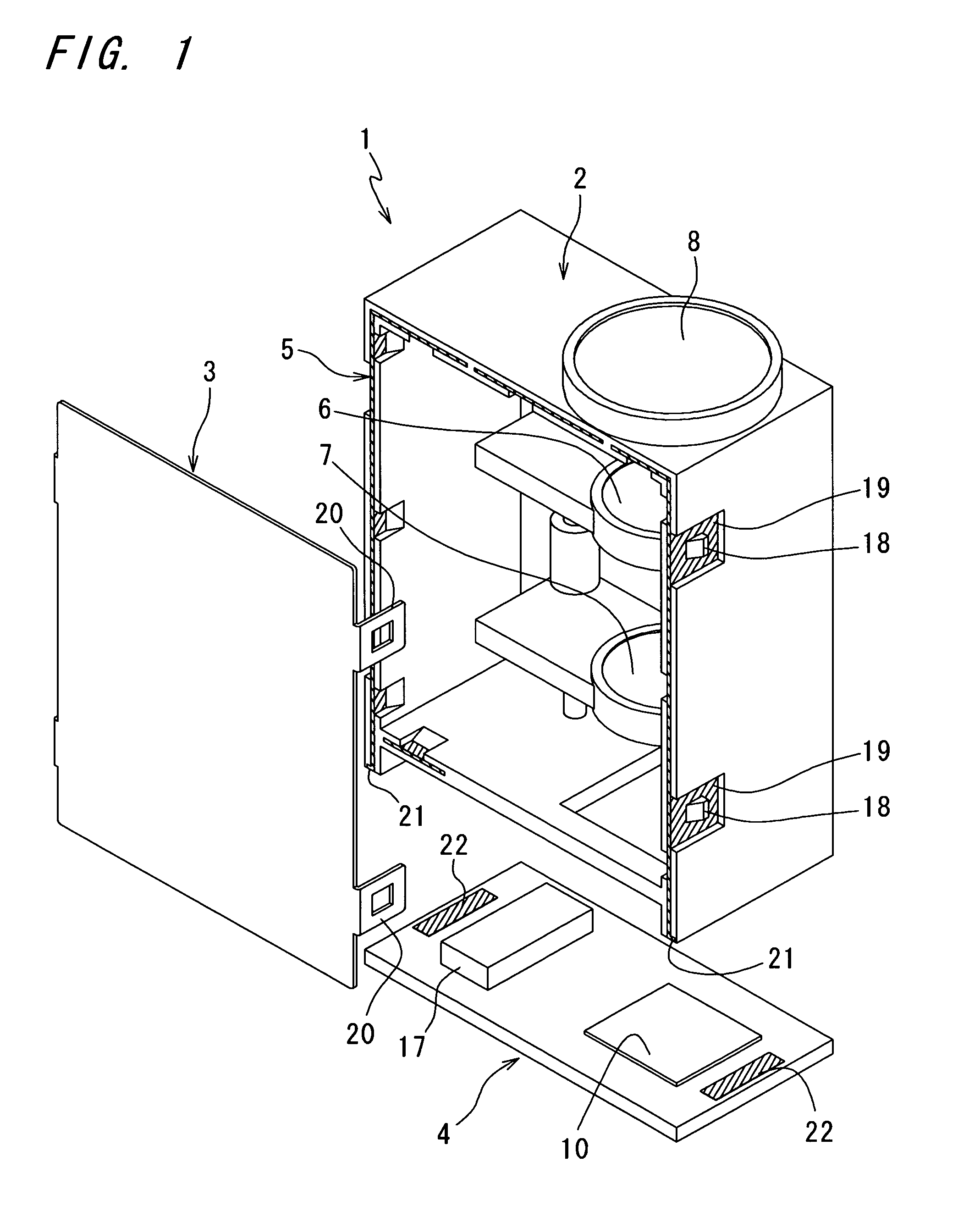
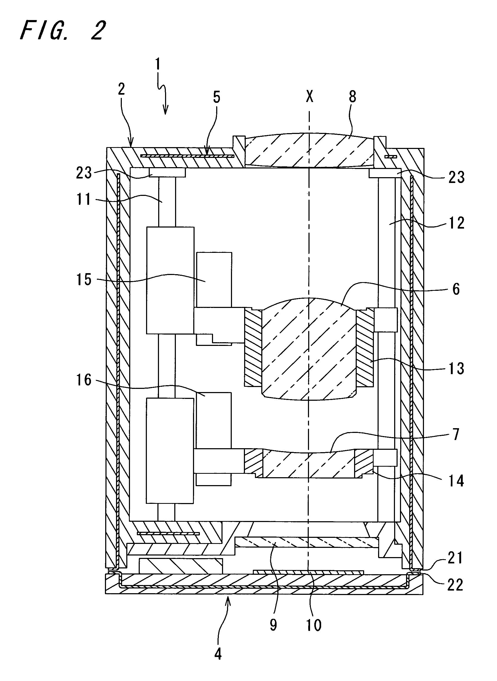
[0021]FIGS. 1 and 2 show a camera module 1 in accordance with the invention. The camera module 1 is composed of a housing 2 generally shaped like a box with one face opened, a lid 3 for sealing the opened part of the housing 2, and a substrate 4 fixed to the housing 2.

[0022]The housing 2 is produced by press working of a metal plate 5 that is made of a steel plate having a thickness, e.g., not larger than 0.3 mm and shown in a development of FIG. 3 and that is made generally into shape of the box, and by formation of resin layers on both outer and inner surfaces of the metal plate 5 by injection molding. The housing 2 is in shape of the box of which the one face having the largest area is opened, and defines an inside space that accommodates an optical system composed of a group of lenses including lenses 6, 7 having an optical axis X parallel to the opened face. All surfaces (walls) of the housing 2 include the metal plate 5 at least partially. In the housing 2, an opening that hol...

second embodiment

[0043]As an example, FIG. 9 shows a cellular phone 50 in which the camera module 1 of the second embodiment is l ed. As shown, the invention makes it possible to install a camera module having advanced functions such as optical zooming and auto focus in an electronic device such as thin-shaped cellular phone.

[0044]As described above, the camera module of the invention has the housing which is molded from resin so that the layers of the resin are formed on both sides of the metal plate and in which the inside space for accommodating the group of lenses is formed and that is opened at least in one direction, the lid for sealing the opened part of the housing, and the substrate on which the imaging element is mounted.

[0045]In this configuration, the housing can be provided with electromagnetic shieldability and strength by resin molding with insertion of the metal plate. Details of the shape of the housing are defined by the resin having undergone the molding, and a high dimensional ac...


PUM


Abstract

There is provided an inexpensive camera module 1 having shieldability. The camera module 1 has a housing 2 which is molded from resin so that layers of the resin are formed on both sides of a metal plate 5 and in which an inside space for accommodating a group of lenses 6, 7 is formed and which is opened at least in one direction, a lid 3 for sealing the opened part of the housing 2, and a substrate 4 on which an imaging element 10 is mounted. In the housing 2, the metal plate 5 is partially exposed, and the lid 3 composed of conductive material and ground patterns 22 on the substrate 4 are in conductive contact with exposed parts 19, 21 of the metal plate 5.

Description

[0001]This application is based on application No. 2007-198690 filed in Japan, the contents of which are hereby incorporated by reference.BACKGROUND OF THE INVENTION[0002]The present invention relates to a camera module and an electronic device having the camera module.[0003]A camera module, which has imaging elements, electronic components for processing image signals, and the like, is preferably shielded in order that electromagnetic interference therewith from outside may be prevented.[0004]In US 2004 0017501 A1 is disclosed a camera module that is provided with electromagnetic shieldability by formation of a conductive resin layer on a surface of a housing (case) on occasion of molding of the housing. There is a danger, however, that the use of conductive resin may cause unexpected short circuit. Therefore, the use makes it necessary to provide insulating members therein. There are problems in that the insulating members hinder reduction in size of the camera module and make the...

Claims


Application Information

Patent Timeline
Patent Type & Authority Patents(United States)
IPC IPC(8): G03B17/02H04N5/225H04N5/335
CPCG03B17/02H04N5/2252H04N5/2257H04N23/51H04N23/57
Inventor MITANI, YOSHIFUMI
Owner KONICA MINOLTA OPTO
Why Eureka
Try Eureka