
Seat, especially an airplane or vehicle seat

a seat and airplane technology, applied in the field of seats, can solve the problem of increasing and achieve the effect of improving the risk of thrombosis for the seat occupan

Inactive Publication Date: 2010-10-05
RECARO AIRCRAFT SEATING
View PDF14 Cites 16 Cited by
  • Summary
  • Abstract
  • Description
  • Claims
  • Application Information

AI Technical Summary

Benefits of technology

[0004]An object of the present invention is to provide a seat, especially an aircraft or other vehicle seat, which can be universally used and which does not have the described disadvantages in the prior art, especially by helping to avoid the danger of thromboses for long passages or trips.
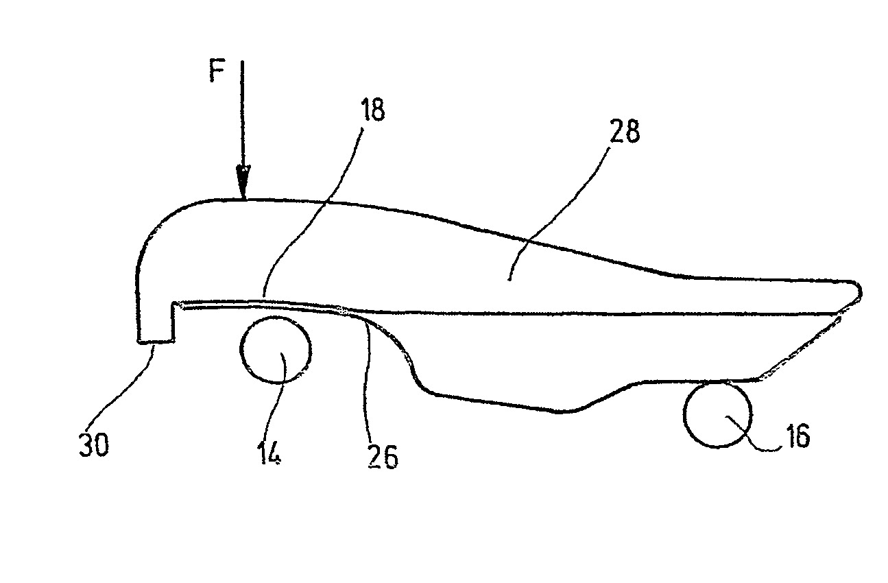
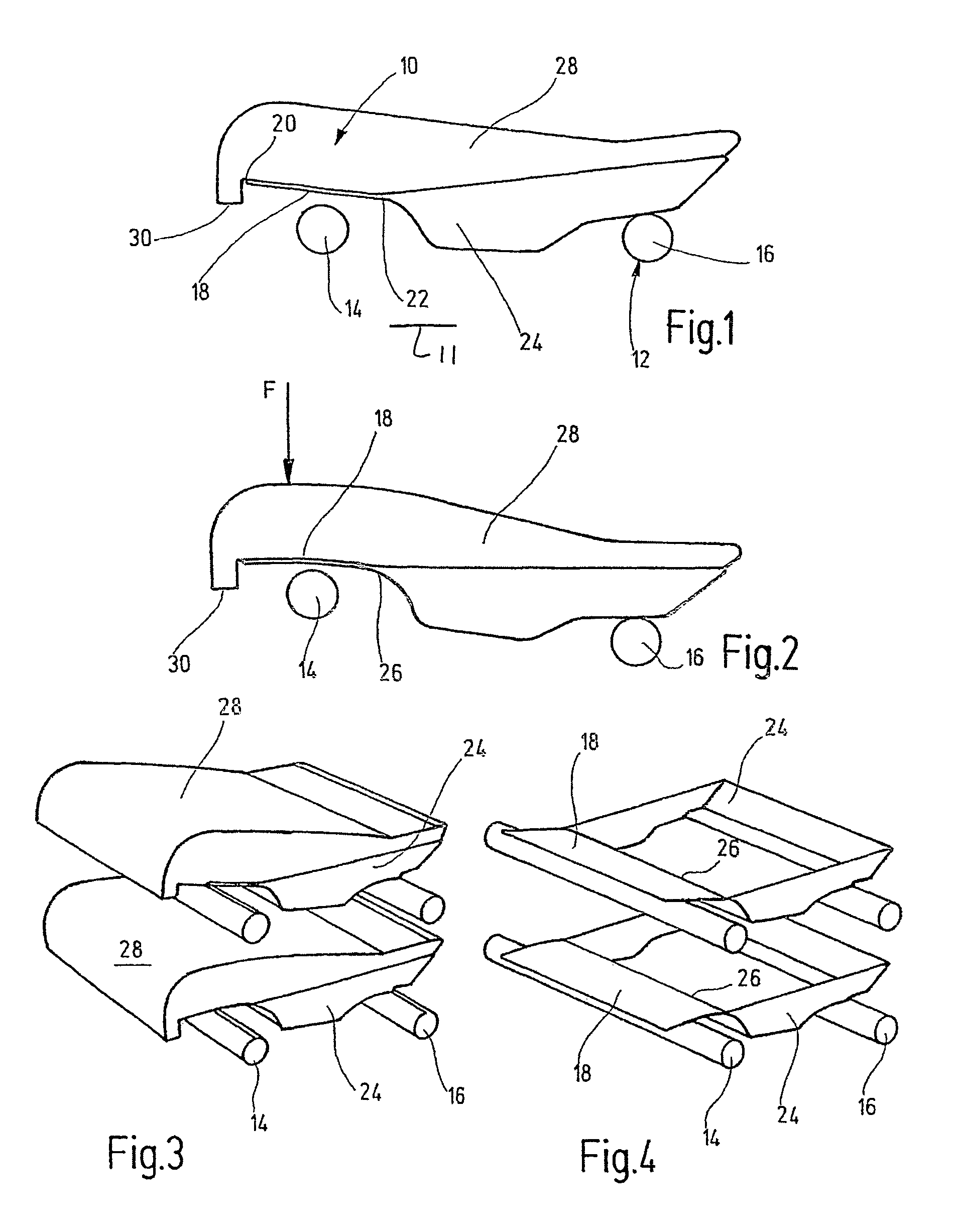
[0005]This object is basically achieved by a seat where its supporting part is made flexible, and at a definable seat load, can be moved in the direction of the seat structure. When unloaded, the supporting part moves back in the reverse direction away from the seat structure into its initial position. The seat front area is flexibly held, so that, depending on the respective seat load applied by the seat occupant, the front area of the seat part yields. In this way, the seat reduces the compressive forces on the bottom of the thigh of the seat occupant, with the result that the cross sections of the veins in this area are not reduced, and are maintained with the result that blood circulation is not disrupted. Thus, the risk of thrombosis is clearly reduced. With the present invention, a maximum support area of the thigh in any seat position is consequently achieved, while avoiding compressive forces mainly in the forward area of the bottom of the thigh. Furthermore, harmful shearing forces on the bottom of the thigh are also avoided. The pertinent shearing forces which are to be reduced arise especially in the area of the thigh in the reclining position compared to the upright seat position (take-off position) in which a more radically set seat angle is necessary. It is this greater seat angle which causes an increase in the pressure on the bottom of the thigh when the legs are extended (slough position), with the danger of increasing the risk of thrombosis for the seat occupant. The occurrence of these shear forces is reliably avoided by the yielding capacity of the front area of the seat part.
[0006]The pertinent “healthy seat” can also be used in the area of motor vehicles, for example, for busses. Other applications are conceivable in the area of medical treatment chairs, and in dentistry. Furthermore, the comfort of the seat also increases for those seats equipped with pivoting leg and foot rests for relieving the bottom of the thigh. Comfort for these seats, certainly in the upright position, can also be further enhanced in this way.
[0007]In one preferred embodiment of the seat of the present invention, the flexible supporting part is designed as a spring which can be freely moved with one end and with its other end fixed on elements of the seat part and / or of the support structure. If this spring is designed as a rectangular leaf spring, this design can be regarded as a loaded, free rest, the bending stress assuming its highest values at the bearing point and decreasing uniformly with increasing distance from the latter. Preferably, the supporting part in its flexible configuration is made of a thermoplastic, but preferably of a fiber composite, especially a fiber composite fabric which is furthermore preferably an integral component of a seat shell which bears the foam cushion of the seat part. In this way, it also contributes to the comfort of sitting for the seat occupant.

Problems solved by technology

It is this greater seat angle which causes an increase in the pressure on the bottom of the thigh when the legs are extended (slough position), with the danger of increasing the risk of thrombosis for the seat occupant.

Method used


Image

  • Seat, especially an airplane or vehicle seat
  • Seat, especially an airplane or vehicle seat

Examples


Embodiment Construction

[0013]The seat of the present invention is configured especially as an aircraft seat, preferably a passenger seat. In FIG. 1, in a side view, essentially only the seat part 10 of the overall seat is illustrated. In particular, for the sake of simplification, the backrest and / or any foot and leg rests are not shown. The pertinent seat part 10 is accordingly mounted upright or above, relative to a vehicle floor or aircraft cabin deck (not shown) vertically by the seat structure 12. Of the actual seat structure 12 shown in FIG. 1, only the two upper cross members are shown as support members 14, 16. On its front area adjacent the front support member 14 the seat part 10 has a flexibly made supporting part 18. At a definable seat load F (cf. arrow in FIG. 2), supporting part 18 moves in the direction of the seat structure 12, especially in the form of the front support member 14. When relieved accordingly, the flexible supporting part 18 consequently returns from its position shown in F...


PUM


Abstract

A seat, especially an airplane or vehicle seat, has a seat part placed on the stand-type seat structure (12) in relation to a base and provided with a bearing part (18) on its front side. The bearing part (18) is embodied in a flexible manner and can move in the direction of the seat structure (12) when a predefined seating load is exerted on it. When the load is discharged, it can move back into its initial position in the opposite direction from the seat structure (12). This arrangement creates a seat whose front part is maintained in a flexible manner such that the front area of the seat part yields according to the seating load exerted by the seat user. The pressure forces are limited to the lower side of the upper thighs of the seat user. As a result, the cross-sections of the veins in that region are not reduced, but are maintained such that the circulation of the blood is not impeded, significantly reducing the risk of thrombosis.

Description

FIELD OF THE INVENTION[0001]The present invention relates to a seat, especially an airplane or vehicle seat, with a seat part mounted upright on a seat structure relative to the floor and provided with a supporting part on its front.BACKGROUND OF THE INVENTION[0002]Especially on very long passages or trips, such as long-distance flights, but also on cruises, for example, by ferries, a general object of the aircraft and ferry outfitters is to increase the comfort of seat occupants and, accordingly, of the passengers who are to be transported. Especially in first class and business class, the customers have corresponding ideas about what they want, which wishes are to be satisfied. A trend among passengers is to be able to use the travel time for meaningful rest or sleeping, in order, for example, to effectively counteract jet lag at the destination for long-distance flights or the like.[0003]DE 100 91 484 A1 discloses a vehicle seat, especially an aircraft passenger seat, with a seat...

Claims


Application Information

Patent Timeline
Patent Type & Authority Patents(United States)
IPC IPC(8): A47C7/14B60N2/02B60N2/62A47C7/02B64D11/06
CPCB60N2/62B64D11/0607B64D11/06Y02T50/46B64D11/0649Y02T50/40
Inventor FORGATSCH, OLIVERSCHURG, HARTMUTACHILLES, SVEN
Owner RECARO AIRCRAFT SEATING
Learn More