Automatic balancing device and system for centrifuge rotors

a centrifuge and rotor technology, applied in pipeline systems, centrifuges, thin material processing, etc., can solve the problems of lateral motion and significant vibration of the centrifuge chassis, and achieve the effect of reducing resonance speed, high mass inertial coupling, and reducing energy

Inactive Publication Date: 2010-10-05
HOWELL GARY W +1
View PDF38 Cites 6 Cited by
  • Summary
  • Abstract
  • Description
  • Claims
  • Application Information

AI Technical Summary

Benefits of technology

[0013]The present invention is a device and method for automatically balancing centrifuge rotors. More specifically, the present invention provides automatic critically-damped inertial mass centering of a centrifuge rotor to accommodate unbalanced loads without imparting significant vibration on the centrifuge chassis and without lateral frictional damping. A centrifuge rotor shaft is “softly coupled” to a motor drive shaft using a flexible coupling or bellows to allow the rotor to automatically adjust its spin axis from its center of geometry to its new rotational center of mass (e.g., mass centering) in the presence of an unbalanced load. However, the lateral motion needed to mass center the unbalanced load results in lateral energy within the rotor. This lateral motion can impart significant vibration to the centrifuge chassis as a result of overshoot and oscillations (e.g., an under-damped condition) during mass centering if it is not damped. Thus, the present invention also provides an inertial coupling mounted, via a bearing, on the rotor shaft between the rotor and the flexible bellows. This provides inertial critical damping of the mass centering action of the rotor and provides “virtual mass” to the rotor without increasing the polar moment of inertia (e.g., resistance to turning) of the rotor. The movable relatively high mass inertial coupling, in conjunction with the flexible bellows coupling, also enables a lower resonance speed for the centrifuge rotor, thus allowing the centrifuge rotor to transcend resonance with lower energy. As a result, the inertial coupling, and thus the rotational center or mass of the rotor, is free to move laterally without imparting significant vibration on the centrifuge chassis and without imparting vibration that prevents the velocity of the rotor from passing through resonance and reaching slew.
[0014]According to one embodiment of the present invention, the inertial coupling distributes its mass in close vertical proximity to the rotor and is attached via a bearing to the rotor shaft. This allows the inertial coupling to provide virtual mass to the rotor without turning at the same velocity and, thereby, without increasing the polar moment of inertia of the rotor. The inertial coupling is further attached via a clamping collar to a circular horizontal flange of the centrifuge chassis. Ball bearings are provided within bearing races in the inertial coupling and the clamping collar and are compressed against the circular horizontal flange by the clamping collar attachment to the inertial coupling. The ball bearings allow the inertial coupling to move horizontally with inertial resistance and to limit the effects of vertical force vectors and cantilevered moments. The clamping collar provides horizontal travel limiting to bound movement of the inertial coupling. An elastomeric cushion is also provided to soften the impact of the inertial coupling when it comes into contact with the chassis of the centrifuge. The elastomeric cushion absorbs energy during mass centering without imparting a rebound force to the inertial coupling and reduces vibration that may be imparted to the chassis of the centrifuge upon contact of the inertial coupling with the chassis. The elastomeric cushion may be made of a low-density open or closed cell foam of a monomer such as polyurethane.
[0015]According to another embodiment of the present invention, rotational frictional damping of the inertial coupling is provided by use of rods made of a low friction monomer, such as polytetrafluoroethylene (PTFE) or olefin. The rods are placed in contact with a surface of the inertial coupling to lightly inhibit rotation of the inertial coupling. The rods may be pressed against the inertial coupling, for example, using force provided by compressed springs. Alternatively, higher friction materials, such as polyurethane, may be used for tuning purposes where higher frictional damping may be required. Additionally, materials, such as high-density wool felt in conjunction with silicone oil and polyetheretherketone (PEEK), may also be used. Reliability of the centrifuge may be improved by decreasing excessive rotation of the inertial coupling using the rods.

Problems solved by technology

However, the lateral motion needed to mass center the unbalanced load results in lateral energy within the rotor.
This lateral motion can impart significant vibration to the centrifuge chassis as a result of overshoot and oscillations (e.g., an under-damped condition) during mass centering if it is not damped.

Method used


Image

  • Automatic balancing device and system for centrifuge rotors
  • Automatic balancing device and system for centrifuge rotors
  • Automatic balancing device and system for centrifuge rotors

Examples


Embodiment Construction

[0030]The embodiments set forth below represent the necessary information to enable those skilled in the art to practice the invention and illustrate the best mode of practicing the invention. Upon reading the following description in light of the accompanying drawing figures, those skilled in the art will understand the concepts of the invention and will recognize applications of these concepts not particularly addressed herein. It should be understood that these concepts and applications fall within the scope of the disclosure and the accompanying claims.

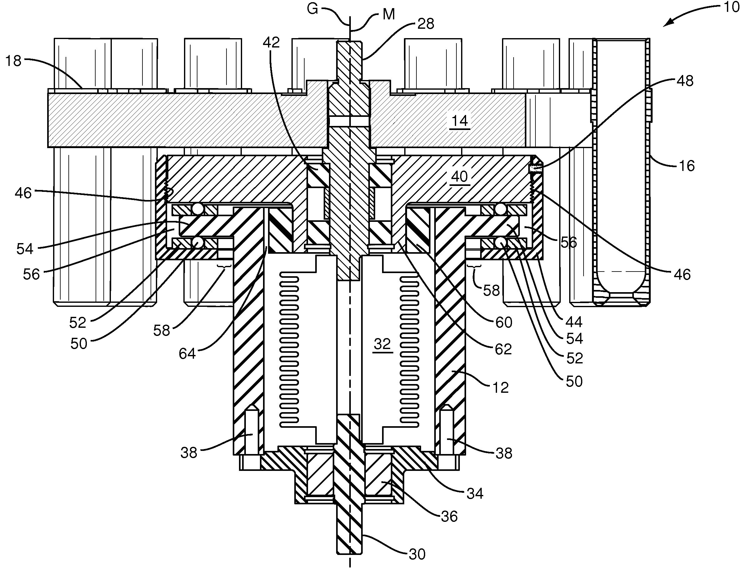
[0031]The present invention is a device and method for automatically balancing centrifuge rotors. More specifically, the present invention provides automatic critically-damped inertial mass centering of a centrifuge rotor to accommodate unbalanced loads without imparting significant vibration on the centrifuge chassis. A centrifuge rotor shaft is “softly coupled” to a motor drive shaft using a flexible coupling or bellows to allow...


PUM


Abstract

An apparatus and method for automatic balancing and inertial damping of vibrations in a rotor are disclosed. According to one embodiment, a rotor drive shaft is adapted to mount a rotor and rotate the rotor. A lower drive shaft connects to a source of rotation. A flexible coupling attaches the rotor drive shaft to the lower drive shaft and transfers a rotational force applied by the source of rotation to the rotor while permitting relative lateral motion between the rotor drive shaft and the lower drive shaft. An inertial coupling is coupled to the rotor drive shaft and provides inertial resistance to the relative lateral motion. A clamping collar is coupled to the inertial coupling to couple the inertial coupling to a chassis and permit the relative lateral motion between the rotor drive shaft and the lower drive shaft.

Description

FIELD OF THE INVENTION[0001]The present invention relates to an automatic balancing centrifuge that does not require load balancing of tubes placed in the centrifuge. More specifically, the present invention provides automatic critically-damped inertial mass centering of a centrifuge rotor to accommodate unbalanced loads without imparting significant vibration on the centrifuge chassis.BACKGROUND OF THE INVENTION[0002]A centrifugation device, often referred to as centrifuge, is used to separate laboratory specimen samples into component parts. For example, blood includes liquid, cells and other components. By spinning the specimen samples within the centrifuge at high velocity, such as 3,000 revolutions per minute (RPM), the samples are separated into the respective component parts based upon relative specific gravity of the components within the samples. When a sample includes components with differing specific gravities, the heavier components are forced to the bottom of the centr...

Claims


Application Information

Patent Timeline
Patent Type & Authority Patents(United States)
IPC IPC(8): B04B9/14
CPCB04B9/08B04B9/12B04B9/14F16F15/36Y10T137/0391
Inventor HOWELL, GARY WAYNE
Owner HOWELL GARY W
Why Eureka
Try Eureka