
Ultrasound breast screening device

a breast screening and ultrasonic technology, applied in the direction of instruments, patient positioning for diagnostics, applications, etc., can solve the problems of x-ray mammography, various patient comfort issues, pain and overall discomfort,

Inactive Publication Date: 2010-10-05
GENERAL ELECTRIC CO
View PDF98 Cites 4 Cited by
  • Summary
  • Abstract
  • Description
  • Claims
  • Application Information

AI Technical Summary

Benefits of technology

"The present invention provides a breast imaging and display system that includes a central processing unit (CPU), an imaging workstation, and an ultrasound breast imaging assembly. The ultrasound breast imaging assembly includes upper and lower compression plates, a breast compression area, at least one pivot assembly, and an ultrasound probe. The system allows for relative motion between the upper and lower compression plates while the planes of the plates are angled with respect to each other. The system also includes an upright member and sonolucent compression film on one compression plate and a sound absorbing stabilization plate on the other compression plate. The upper and lower extension members may translate over the upright member. The system can be used with an x-ray mammography system and the CPU can display an ultrasound image and an x-ray mammographic image on the same monitor. The technical effects of the invention include improved breast imaging and diagnosis using ultrasound and x-ray mammography techniques."

Problems solved by technology

X-ray mammography, however, poses various patient comfort issues.
The force of the compression, and the orientation of the compressing members, may cause pain and overall discomfort.
Additionally, x-ray mammography may be hazardous due to the fact that x-ray mammography uses ionizing radiation.
Further, studies have shown that mammography generates false positives in more than 10% of patients and that that x-ray mammography is not always effective and accurate with respect to dense breasted women because lesions masked by dense breast tissue may go undetected.
However, two separate imaging procedures, that is, x-ray mammography and ultrasound breast imaging, are required for a single patient, which is inconvenient and may even delay diagnosis.
Further, the dual use of x-ray mammography and ultrasound breast imaging requires skilled specialists and typically at least twenty minutes of screening time.
A drawback of such freehand examinations, when used to supplement mammography, is the inability to provide geometric registration between the mammogram and ultrasound images.
The lack of registration makes it difficult to relate what is seen in the ultrasound image to what is seen in the mammogram.
However, the force needed to properly flatten the breast often causes the patient pain and discomfort.
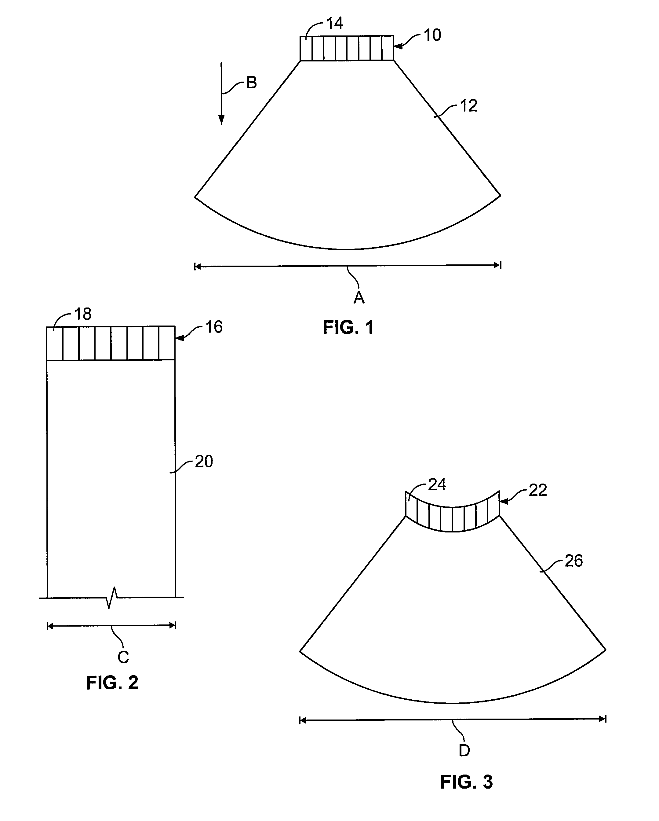
As is well known, using a single row of elements limits the focusing ability of the transducer elements in the near and far fields.

Method used


Image

  • Ultrasound breast screening device
  • Ultrasound breast screening device
  • Ultrasound breast screening device

Examples


Embodiment Construction

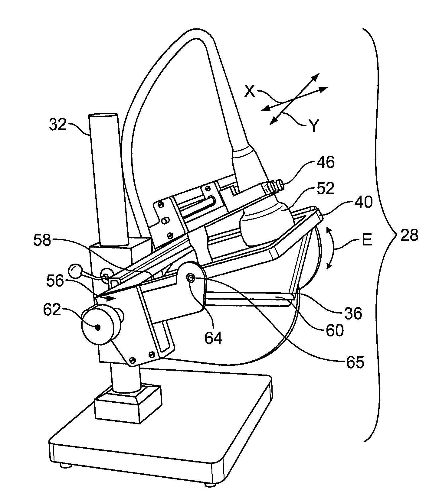
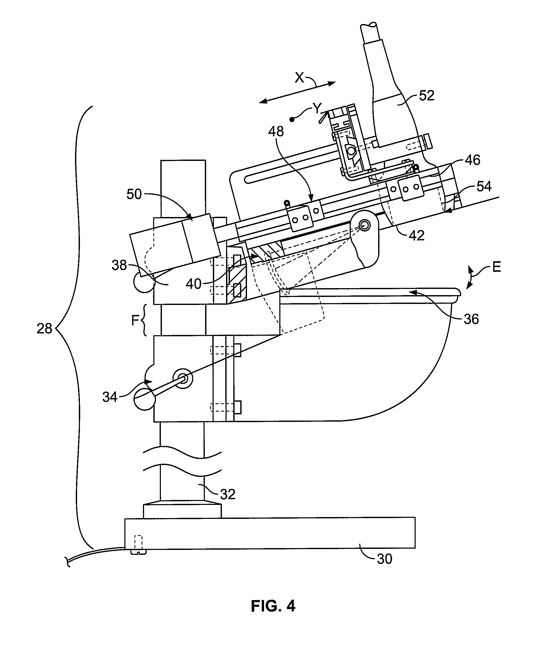
[0045]FIG. 15 is a schematic diagram of an ultrasound imaging system 100 according to an embodiment of the present invention. The ultrasound imaging system 100 includes an ultrasound imaging device 28, which is in electrical communication with a central processing unit (CPU) 102. The CPU 102 may control movement of an imaging transducer (discussed below) and the movement of compression plates (discussed below) of the ultrasound imaging device 28. The CPU 102 sends control commands to the ultrasound imaging device 28, and receives data signals from the ultrasound imaging device 28. The CPU 102 analyzes the data signals received from the ultrasound imaging device in order to form images for display. The CPU 102 is also in electrical communication with an imaging workstation 104, which displays image data received from the CPU 102. That is, the CPU 102 may send signals to, and receive signals from, the imaging workstation 104. A user may enter imaging and display commands through input...


PUM


Abstract

An ultrasound breast imaging assembly includes first and second compression plates angled with respect to one another, a breast compression area defined between the first and second compression plates, at least one pivot assembly, and an ultrasound probe. The pivot assembly allows relative motion between the first and second compression plates. The ultrasound probe, which is configured to translate over one of the first and second compression plates, includes an active matrix array (AMA) positioned on one of the first and second compression plates.

Description

RELATED APPLICATIONS[0001]This application claims the benefit of U.S. Provisional Application No. 60 / 453,644, filed Mar. 11, 2003, titled “Integrated Auto-Scan, Full Field 3D Ultrasound Breast Screening Device,” which is hereby expressly incorporated herein in its entirety.BACKGROUND OF THE INVENTION[0002]Embodiments of the present invention generally relate to ultrasound breast screening systems, and more particularly to ultrasound breast screening systems having automated ultrasound transducers positioned on at least one compression plate.[0003]Typically, x-ray mammography is used as the primary screening procedure for detection of breast lesions. For each x-ray mammogram screening of a patient, a top view, referred to as a cranio-caudal view (“CC” view), and a mediolateral oblique view (“MLO” view) are usually taken.[0004]X-ray mammography, however, poses various patient comfort issues. For example, a patient's breast is typically compressed during a mammographic procedure. The f...

Claims


Application Information

Patent Timeline
Patent Type & Authority Patents(United States)
IPC IPC(8): A61B8/00A61B8/08G01S7/521G01S15/89
CPCA61B8/0825A61B8/42A61B8/4218G01S7/52079G01S15/899G01S15/8915G01S15/8938A61B6/502A61B8/4416
Inventor ZHANG, HEIDI D.LAWRENCE, ROBERT F.LIMA, GILBERT M.MILLER, STEVEN C.HALL, ANNE L.
Owner GENERAL ELECTRIC CO
Learn More