Control apparatus for electric train

a technology for controlling apparatus and electric trains, applied in the direction of motor/generator/converter stopper, dynamo-electric converter control, ventilation system, etc., can solve the problems of large control apparatus size, high fabrication cost, and wear of brake shoes

Inactive Publication Date: 2010-10-05
MITSUBISHI ELECTRIC CORP
View PDF28 Cites 6 Cited by
  • Summary
  • Abstract
  • Description
  • Claims
  • Application Information

AI Technical Summary

Benefits of technology

[0011]In the control apparatus for the electric train according to the first viewpoint of this invention, the load control means receives the inverter state signal representative of the operation state of the variable-voltage variable-frequency inverter from it, and the control means controls the load connected to the auxiliary power source device, in accordance with the inverter state signal, so that the regenerative energy of the DC power feed circuit can be consumed by the load of the auxiliary power source device without disposing a brake chopper or an electric-double-layer capacitor in the DC power feed circuit.
[0012]In the control apparatus for the electric train according to the second viewpoint of this invention, the load control means receives the DC power feed information of the DC power feed circuit, and it controls the load connected to the auxiliary power source device, in accordance with the DC power feed information, so that the regenerative energy of the DC power feed circuit can be consumed by the load of the auxiliary power source device without disposing a brake chopper or an electric-double-layer capacitor in the DC power feed circuit.

Problems solved by technology

In this case, however, a brake shoe wears off due to the mechanical braking, and hence, the maintenance of the brake shoe needs to be performed in a certain fixed period.
Since, however, the brake chopper is added to a control apparatus in this case, there has been the problem that the control apparatus becomes large in size and high in fabrication cost.

Method used


Image

  • Control apparatus for electric train
  • Control apparatus for electric train
  • Control apparatus for electric train

Examples


embodiment 1

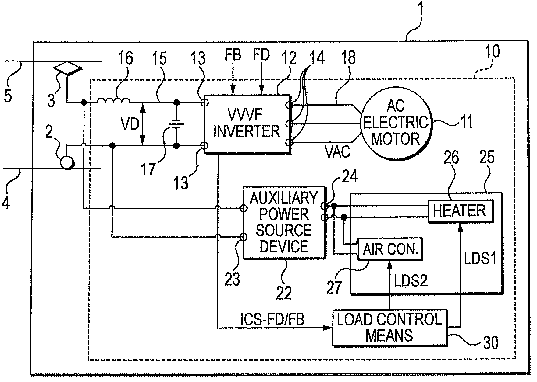
[0014]FIG. 1 is a block diagram showing Embodiment 1 of a control apparatus for an electric train according to this invention. The control apparatus 10 for the electric train in Embodiment 1 is the control apparatus installed in the electric train 1. The electric train 1 includes a wheel 2, and a collector shoe 3. The wheel 2 runs on a track 4, and the collector shoe 3 touches an overhead line, that is, a DC power feed line 5 and receives the feed of DC electric power from the DC power feed line 5. The DC power feed line 5 feeds DC electric power to a plurality of electric trains including the electric train 1. The prescribed voltage VD0 of the DC power feed line 5 is set at, for example, 1500 (V) or 750 (V).

[0015]The control apparatus 10 includes an AC electric motor 11, an inverter 12, a DC power feed circuit 15, an AC power feed circuit 18, an auxiliary power source device 22, a load 25, and load control means 30.

[0016]The AC electric motor 11 is the drive source of the electric ...

embodiment 2

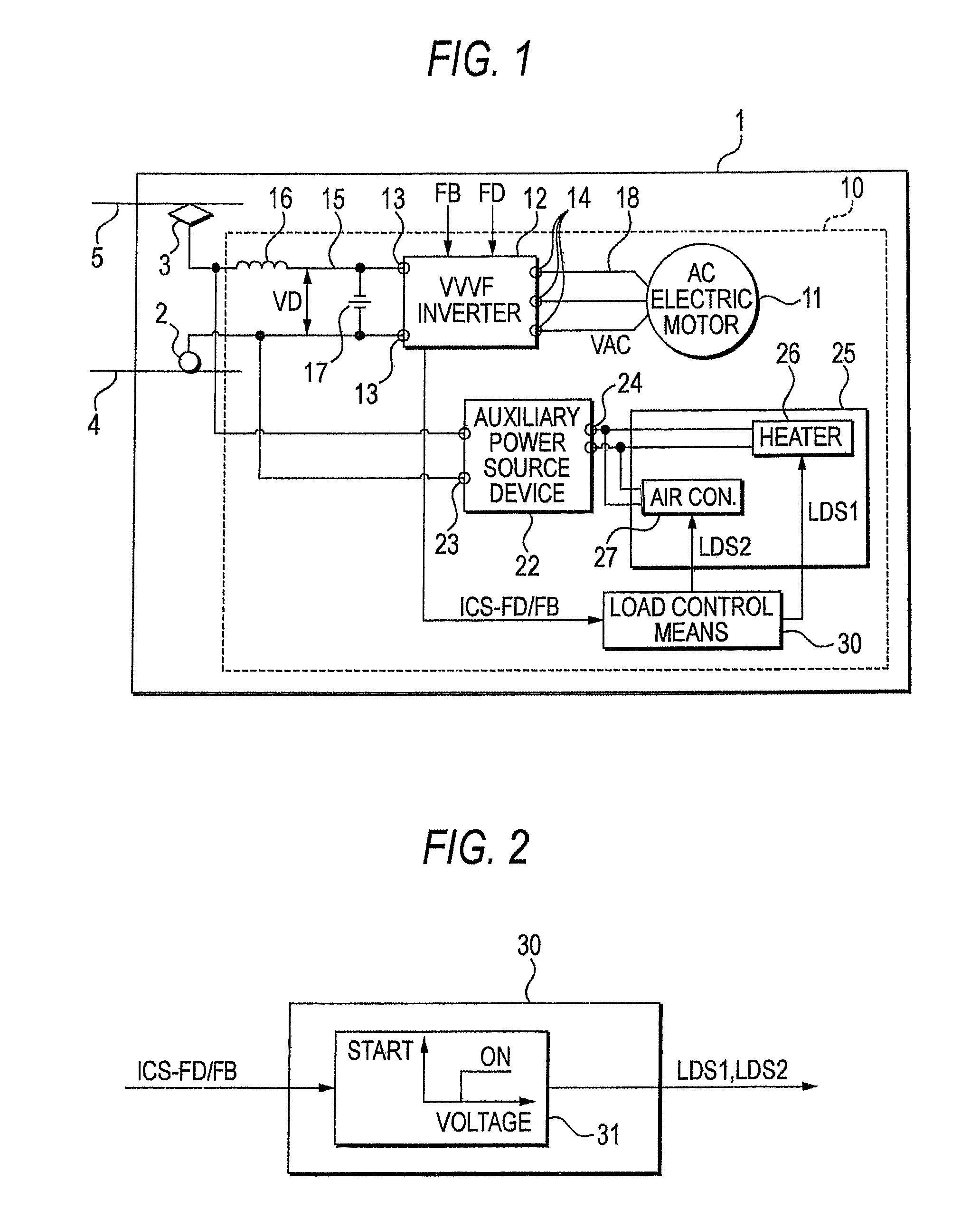
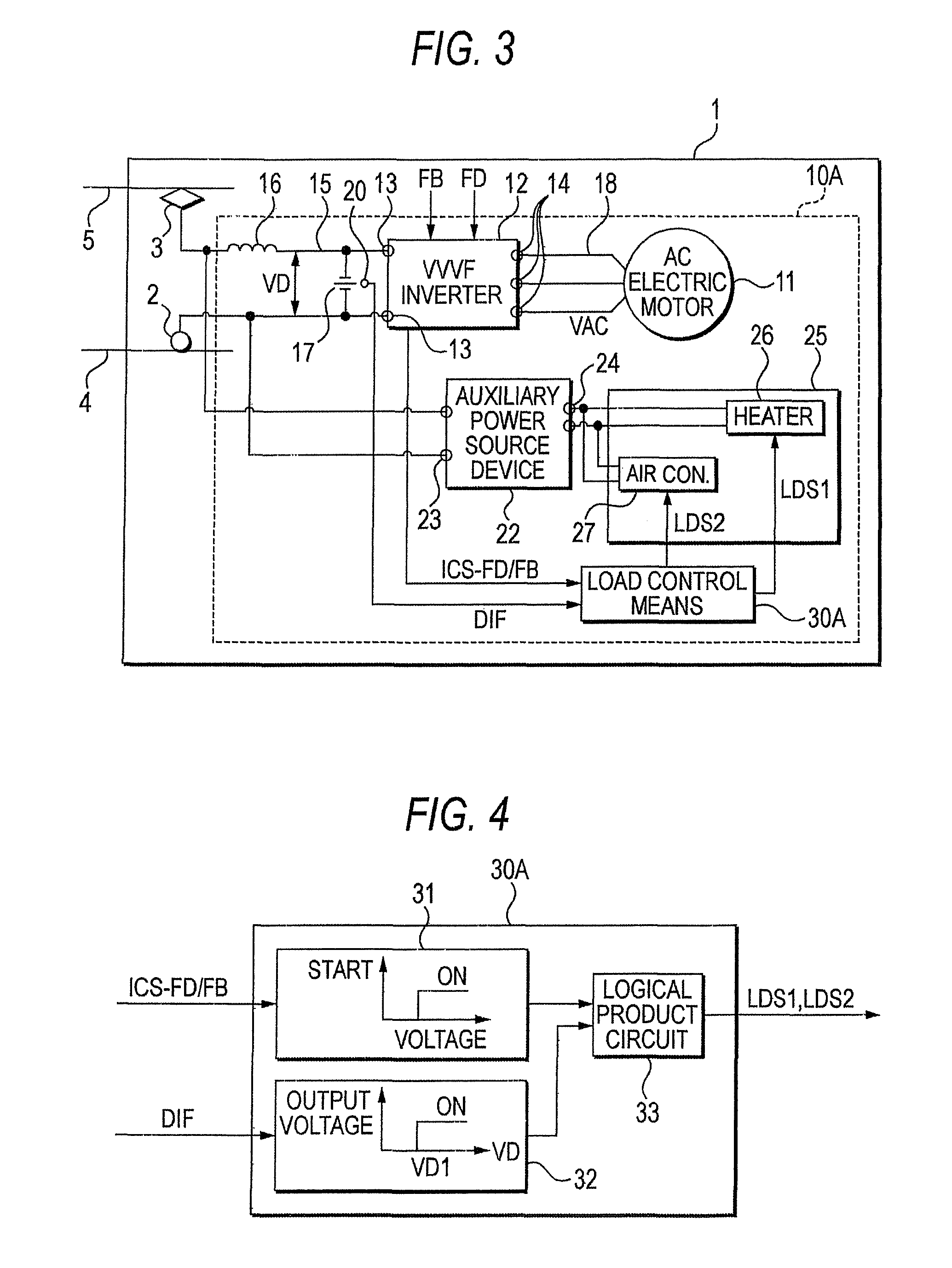
[0030]FIG. 3 is a block diagram showing Embodiment 2 of a control apparatus for an electric train according to this invention, while FIG. 4 is a block diagram showing the details of load control means 30A for use in this embodiment 2.

[0031]In Embodiment 1, the in-room heater 26 and the in-room air conditioner 27 which form the load 25 of the auxiliary power source device 22 are simultaneously ON / OFF-controlled by the load control means 30 on the basis of the inverter state signal ICS-FD / FB, whereas in this embodiment 2, detection means 20 for detecting the DC power feed information DIF of a DC power feed circuit 15 is added to the DC power feed circuit 15, and the in-room heater 26 and the in-room air conditioner 27 which form the load 25 of the auxiliary power source device 22 are simultaneously ON / OFF-controlled by the load control means 30A on the basis of the inverter state signal ICS-FD / FB and the DC power feed information DIF. The others are configured to be the same as in Emb...

embodiment 3

[0041]FIG. 5 is a block diagram showing Embodiment 3 of a control apparatus for an electric train according to this invention, while FIG. 6 is a block diagram showing the details of load control means 30B for use in this embodiment 3. The control apparatus for the electric train in this embodiment 3 is indicated by reference sign 10B. This control apparatus 10B for the electric train is such that the load control apparatus 30A in Embodiment 2 is replaced with the load control means 30B, and the others are configured to be the same as in Embodiment 2.

[0042]The load control means 30B for use in Embodiment 3 has voltage generation tables 31 and 32 and a logical product circuit 33, likewise to the load control means 30A used in Embodiment 2, but an inverter state signal ICS-FD is inputted to the voltage generation table 31. The inverter state signal ICS-FD is a signal representative of a powering command signal FD which is given to an inverter 12, and this inverter state signal ICS-FD b...


PUM


Abstract

To propose a control apparatus for an electric train, in which the regenerative energy of a DC power feed circuit can be consumed without disposing the brake chopper or electric-double-layer capacitor of the DC power feed circuit.A control apparatus for an electric train according to this invention includes an AC electric motor which drives the electric train, and a variable-voltage variable-frequency inverter which controls the AC electric motor, and further includes an auxiliary power source device connected to a DC power feed circuit, and load control means for controlling a load connected to the auxiliary power source device, wherein the load control means receives an inverter state signal representative of an operation state of the variable-voltage variable-frequency inverter from the it, and the load control means controls the load in accordance with the inverter state signal. Besides, the control apparatus for the electric train includes detection means for detecting DC power feed information representative of the DC power feed state of the DC power feed circuit, and the load control means controls the load in accordance with the DC power feed information.

Description

TECHNICAL FIELD[0001]This invention relates to a control apparatus for an electric train, wherein an AC electric motor is used as a drive source, and the AC electric motor is controlled by a variable-voltage variable-frequency inverter.BACKGROUND ART[0002]In case of an electric train, during ordinary braking, electrical braking based on regenerative braking is performed to convert the inertial energy of a vehicle into electric energy, and to restore the regenerative energy to an overhead line, that is, a DC power feed line. In the regenerative braking, it is indispensable that the side of the DC power feed line has a regenerativity, or that another electric train under power running as acts as a regenerative load exists on the DC power feed line side.[0003]Here, in a case where the regenerative energy of the electric train in the regenerative braking state is greater than power which is consumed by the electric train in the power running state, the voltage of the overhead line or th...

Claims


Application Information

Patent Timeline
Patent Type & Authority Patents(United States)
IPC IPC(8): H02P7/00B60L3/00B60L7/12
CPCB60L7/14B60L9/22B60L2200/26B60L2210/20H02P3/18H02P29/0241Y02T10/72
Inventor KITANAKA, HIDETOSHIKONO, MASAKI
Owner MITSUBISHI ELECTRIC CORP
Why Eureka
Try Eureka