Method and device for reducing harmonics in power converters

A technology of power conversion and equipment, applied in the direction of converting irreversible DC power input into AC power output, output power conversion device, transportation and packaging, etc.

Inactive Publication Date: 2006-02-15
ALSTOM BELGIUM SA
View PDF6 Cites 1 Cited by
  • Summary
  • Abstract
  • Description
  • Claims
  • Application Information

AI Technical Summary

Problems solved by technology

[0006] However, changing the structure of the system is usually limited by the loss of the semiconductor or the physical properties of the system

Method used


Image

  • Method and device for reducing harmonics in power converters
  • Method and device for reducing harmonics in power converters
  • Method and device for reducing harmonics in power converters

Examples


Embodiment Construction

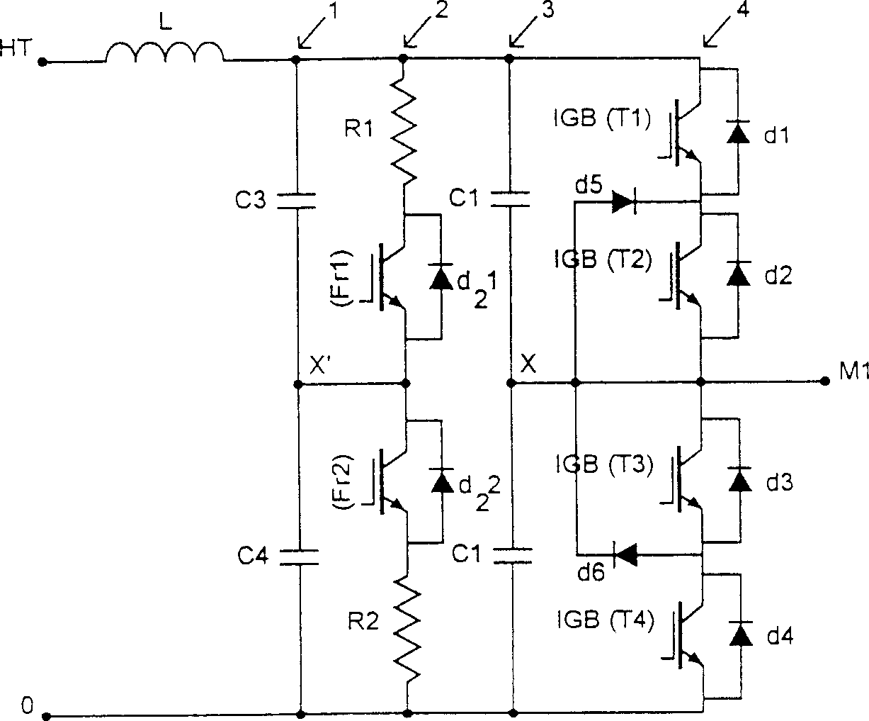
[0027] figure 1 represents a one-two-stage converter according to the prior art. It usually consists of several subsystems: input filter 1, brake chopper 2 and inverter 4. In the present example only one leg of the three-level inverter is shown.

[0028] Typically, the input filter consists of an inductor L and one or more capacitors C3 and C4.

[0029] The brake chopper 2 consists of two switches Fr1 and Fr2, preferably of the IGBT type, connected in series, each of these switches in parallel with a reverse biased diode Dr1 and Dr2, the switch / reverse biased diode assembly In series with resistors R1 and R2 allowing to dissipate energy not dissipated by load M1.

[0030] In addition, to ensure the voltage strength, a capacitor voltage divider for the chopper consisting of two capacitors C3 and C4 is provided.

[0031] One arm of a three-level inverter is usually as figure 1 shown in . It consists of four switches, preferably of the IGBT type, coupled in pairs (T1 and T2...


PUM


Abstract

The invention concerns multistage power switching electronic device for reducing undesirable harmonics amplitudes generated in said device, in particular in the form of beats, comprising at least an input filter (1), a rheostatic braking chopper (2) including at least two switches (Fr1, Fr2) and mutlilevel static converter (4) including at least four switches in series (T1, T2, T3, T4). The invention is characterised in that the oscillator (4) is directly attached to the chopper (2) providing a connection by their midpoint (X = X') and it comprises a variable random frequency pulse generator controlling the switches of said chopper (2).

Description

technical field [0001] The present invention relates to a device and a method for reducing interfering harmonics generated in a power converter. technical background [0002] Power electronics typically operate with switching that causes harmonic generation. In addition, a power system consists of several subsystems that operate at their own frequency. The combination of these different frequencies is the harmonic source of the beat phenomenon. [0003] A beat is a periodic variation in the amplitude of an oscillation produced by the superposition of two adjacent frequencies. [0004] Typically, these subsystems are sought to be decoupled through the use of filters comprising inductors (L) and capacitors (C). [0005] In the case of three-phase inverters for propulsion engines in railway applications, for example, PWM wave processing by set wave correction in phase detectors has been suggested (publication number WO96 / 33548). This process makes it possible to eliminate t...

Claims


Application Information

Patent Timeline
Patent Type & Authority Patents(China)
IPC IPC(8): H02M1/12H02M7/48
CPCH02M1/12B60L7/06B60L2200/26B60L2270/147
Inventor 约汉尼·布萨达
Owner ALSTOM BELGIUM SA
Why Eureka
Try Eureka